Lesson Modules
Teaching Tips:
SECTION 1 – WIRING the MAGIC BOX AND SENSORS – 1st SETUP
Caution: NEVER wire anything to the Magic Box while it has power on. ALWAYS turn it off before making connections or damage to the Controller could occur. Be sure to ask your instructor if you have any questions.
SETUP #1
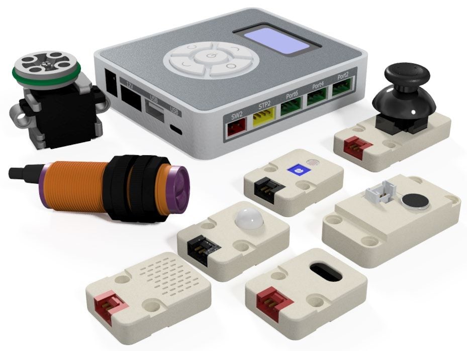
1. For this activity, you will need:
- 1× Magic Box
- 1× USB-A to USB-C Cable
- 1× AC/DC Power Adapter (12 V)
- 5× Common Sensor Cables
- (Photoelectric Sensor does not need a common sensor cable)
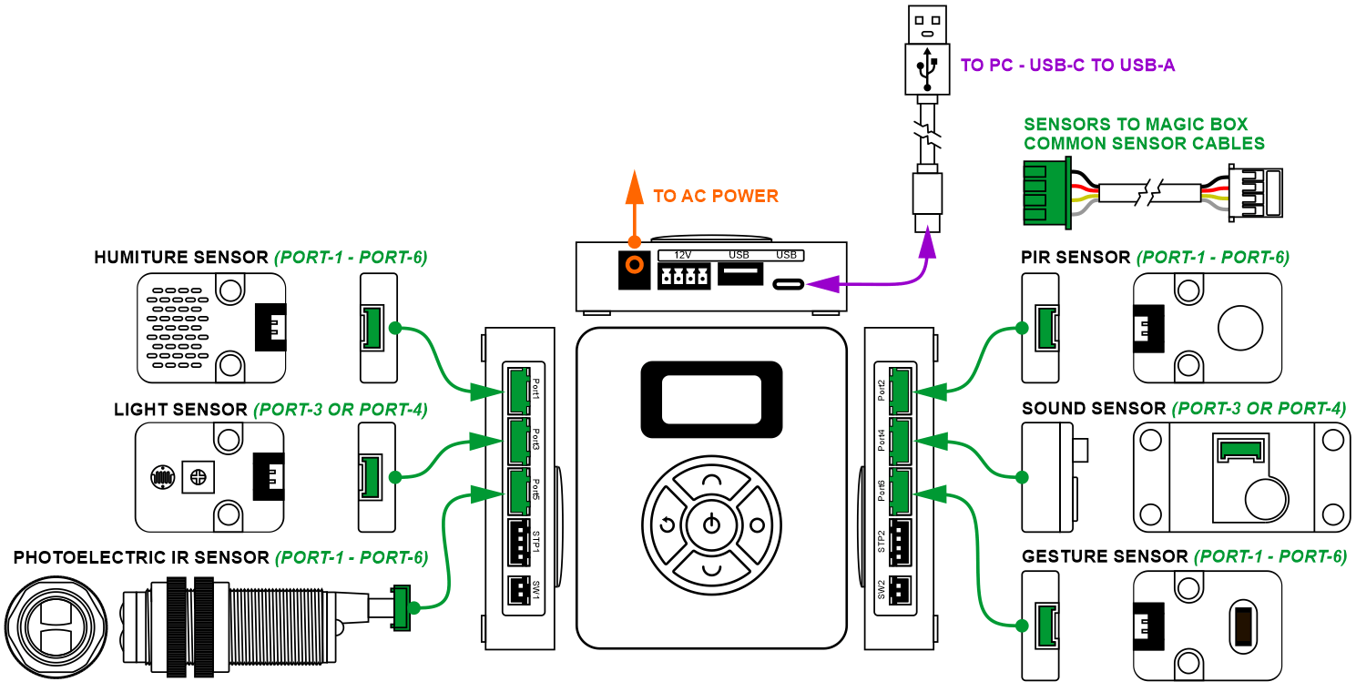
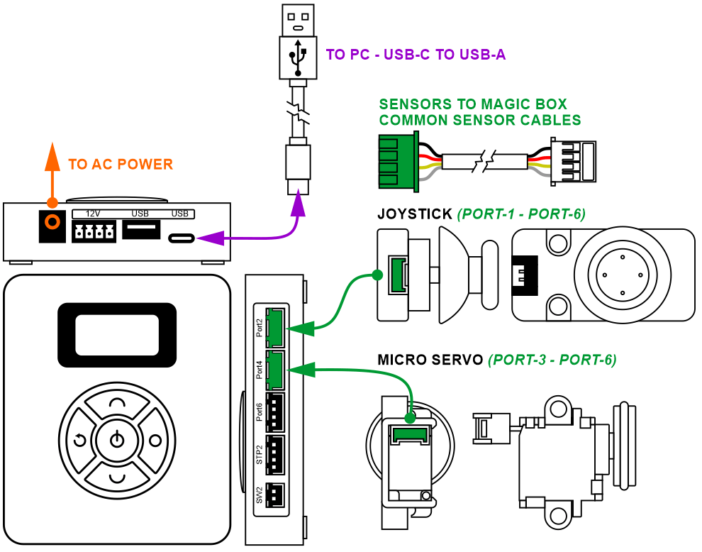
2. Wire the Magic Box as shown below:
- 1× PIR Sensor – PORT 2
- 1× Sound Sensor – PORT 4
- 1× Gesture Sensor – PORT 6
- 1× Humiture Sensor – PORT 1
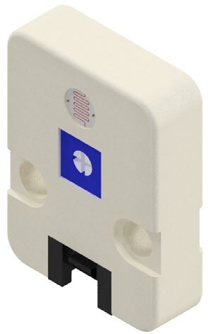
- 1× Light Sensor – PORT 3
- 1× Photoelectric IR Sensor – PORT 5
Caution: MAKE SURE THE TAB IS PRESSED DOWN ON THE WHITE CONNECTOR WHEN DISCONNECTING ALL SENSORS!!! It is very easy to damage the sensors if the white connector is pulled or tugged on without pressing down the small white tab to release the cable from the sensor housing.
SECTION 2 – CONNECTING the MAGIC BOX to DOBOTLAB
1. Open up DobotBlock Lab in the software.


2. Once all of the wiring is done and all of the sensors connected, power ON the Magic Box.

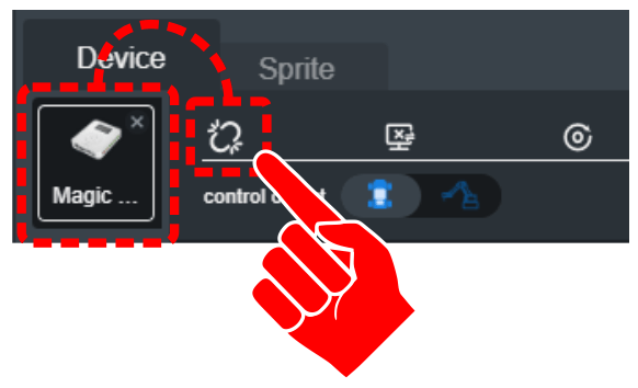
3. Follow the same process from previous activities to add the Magic Box as a device and connect the software to it (establish communication).
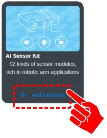
4. Click on “+ Add extension” for the AI SENSOR KIT.
Teaching Tips:
SECTION 3 – SETUP #1 - EXPLORING ADVANCED SENSORS
• PIR, SOUND, GESTURE, HUMITURE, LIGHT, PHOTOELECTRIC
SKILL BUILDER 1 – PIR SENSOR – DIGITAL INPUT
1. The first sensor explored in this activity is the PIR SENSOR. In the software it is referred to as a Human Sensor.
The PIR sensor is a body infrared sensor. It detects the infrared radiation emitted or reflected by the human body or other objects. When the sensor detects infrared it outputs a TRUE signal. It then carries out a time delay (during which the true signal is maintained and repeated triggering is allowed) until the triggering signal disappears (restoring FALSE signal). Note: There is a two-second delay after each detection is triggered.
ANY GREEN PORT – PORT 1-6

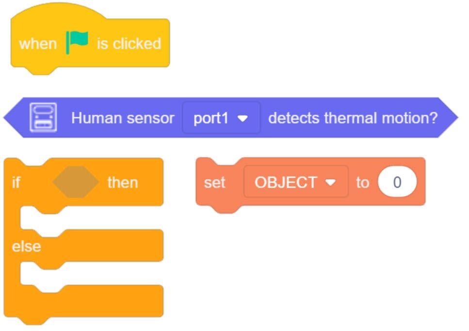
2. Drag over a Human Sensor Detects block from the AI SENSOR KIT toolbox.
This block will produce a TRUE result if thermal motion is detected.
3. Change the PORT value to the correct port (see page 2).
4. A few simple lines of code are needed to retrieve values from the sensors used throughout this activity.
Some of the sensors can be tied to a variable (PILL shaped) and some will need to be used as a condition in a loop (HEX shaped).
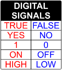
5. This sensor is a digital sensor. It will only report a TRUE/HIGH or FALSE/LOW signal.
The values for this sensor are reported by HEX shapes. Create a variable (OBJECT) and an IF/ELSE Statement.
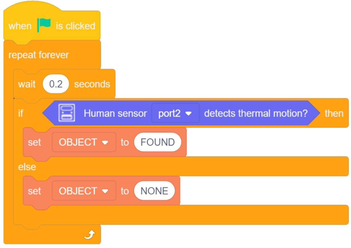
A TRUE condition will change the variable OBJECT to FOUND.
ELSE (not true) the variable will show as NONE.


6. Place everything inside a forever loop with a small micro wait.
7. Download the code to the Magic Box. Practice with this group of code and record your results below.
A. What type of range does the sensor have? (How far can the sensor detect motion?)
B. What type of vision does the sensor have? (Different angles, all the way around?)
C. What type of motion does the sensor detect? (side to side, forward backward, rotation?)
D. After the object is still (no motion) for more than two seconds, what happens?
E. Can the sensor detect motion of an object?
- Ball rolling, does it have to be large (marble?)
- Something tossed across its field of view (did it detect the object or you tossing the object)
F. What happens if the motion is smooth and continuous (rotating fan or oscillating fan, back & forth)
G. Can you or an object move slow enough to keep the sensor from reading TRUE?
SKILL BUILDER 2 – SOUND SENSOR – ANALOG INPUT
1. The second sensor this activity will explore is the SOUND SENSOR.
The sound sensor is used to detect the sound intensity of the surroundings. The greater the sound intensity it receives, the stronger the output signal and the greater the return value is.
PORT 3 or 4
2. Drag over a Sound Intensity Value from the AI SENSOR KIT toolbox.
This sensor is an analog sensor. The values produced by this sensor will increase or decrease depending on the level/intensity of the sound it receives.
3. Change the PORT value to the correct port (see page 2).
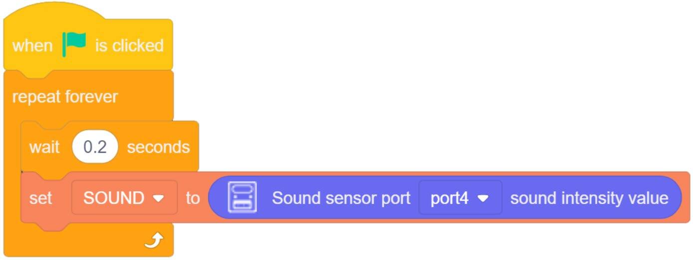
4. (a) The values for this sensor are reported to a PILL shape. Create a variable (SOUND).
4. (b) Add this block to a SET VARIABLE TO (“SOUND”).
5. Place everything inside a forever loop with a small micro wait.
6. Download the code to the Magic Box. Practice with this group of code and record your results on the next page.


B. What analog value is reported when no sound is present?
C. Does the length of time the sound is heard by the sensor change the value?
D. What is the highest value you can get the sensor to report?
E. Document additional observations below.
SKILL BUILDER 3 – GESTURE SENSOR – DIGITAL INPUT
1. The Third sensor this activity will explore is the GESTURE SENSOR.
The gesture sensor is a 3D gesture recognition sensor using an I2C communication interface. It supports eight types of gestures by default and it is suitable for a variety of applications, including non-contact remote control, robot interaction, human-machine interaction games, and gesture lighting control.
ANY GREEN PORT – PORT 1-6

2. Drag over the two main blocks related to the gesture sensor from the AI SENSOR KIT toolbox. NOTE: We will not use the additional block for GESTURES in these activities.
![]() Notice that this sensor has both PILL and HEX Blocks. The GESTURE SENSOR is an intelligent sensor that can report a range of responses. It can be used as a condition for a loop as we did with the PIR Sensor.
Notice that this sensor has both PILL and HEX Blocks. The GESTURE SENSOR is an intelligent sensor that can report a range of responses. It can be used as a condition for a loop as we did with the PIR Sensor.
Example: Is left motion detected (Set variable to TRUE / FALSE). It can also be paired with a variable to report which of the 8 motions is being detected in words (string values).


3. Change the PORT value to the correct port (see page 2).
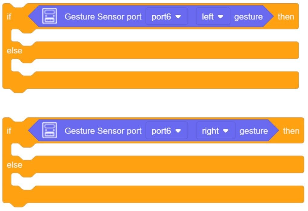
4. Create TWO IF/ELSE Statements.
5. Place a GESTURE TRUE block inside each (one of the set to LEFT is TRUE and one the RIGHT is TRUE).
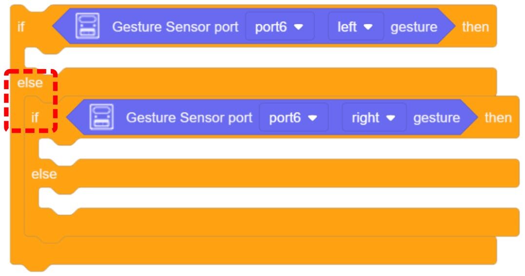
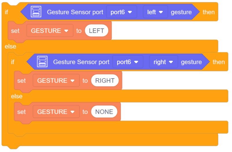
6. The next step will be a new use of the IF/ELSE statement.
Drag the second IF/ELSE into the ELSE condition of the first IF/ELSE.
This creates a condition known as an ELSE-IF. This type of formatting creates a hierarchy or order of importance to the IF statement.
If two conditions could be true at the same time, nesting them in this fashion lets the program make a decision on which operation to do (which is more important). It also allows the program to still contain an ELSE (what to do if no conditions are TRUE).
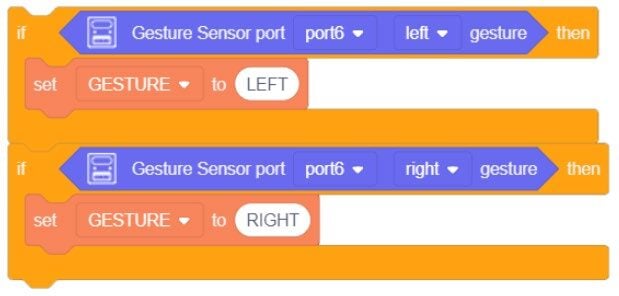
![]() Two IF/ELSE loops will not work for this example. When either condition is not true, the ELSE will always want to set the Variable to NONE.
Two IF/ELSE loops will not work for this example. When either condition is not true, the ELSE will always want to set the Variable to NONE.
![]() Two single IF statements will partially work for this example. Each will clear out the variable when the other becomes true, but nothing will clear out the variable when neither is true. It will start blank (since we did not initialize it to a value), but once either condition is true, it will keep repeating that until told to do something different.
Two single IF statements will partially work for this example. Each will clear out the variable when the other becomes true, but nothing will clear out the variable when neither is true. It will start blank (since we did not initialize it to a value), but once either condition is true, it will keep repeating that until told to do something different.
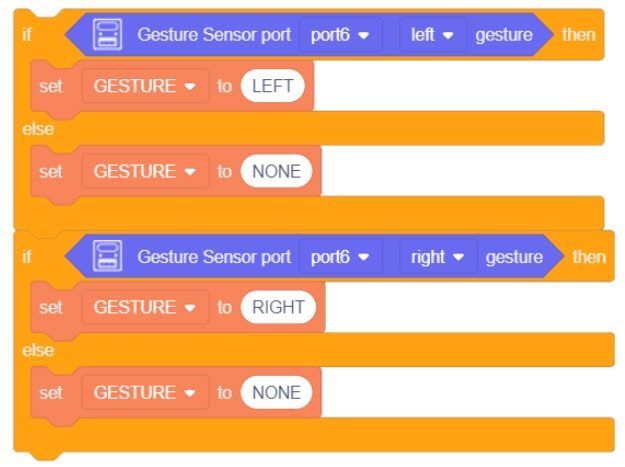
7. Create a new variable (GESTURE) and drag over (or duplicate) three of them (one for each condition).
GESTURE LEFT(Most important, do this if left is true… even if right is also true)GESTURE RIGHT(2nd most important, do this if right is true… as long as left is not true)GESTURE NONE(What to do if LEFT or RIGHT are not TRUE)
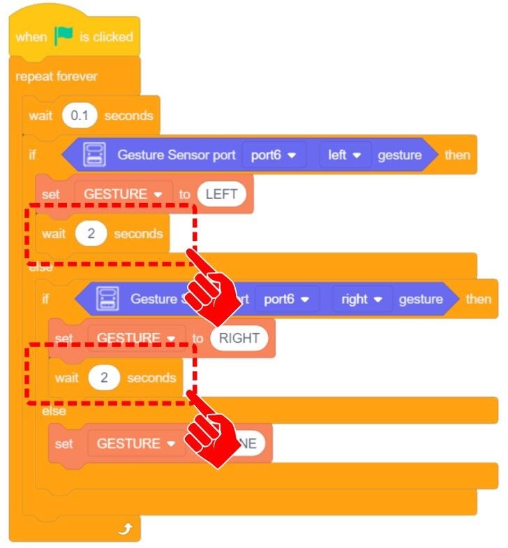
8. Add a WAIT inside the LEFT and RIGHT conditions so the string of text will remain up for a set time before clearing.
9. Place everything inside a forever loop with a small micro wait.
What is the micro wait for?
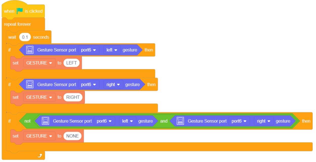
![]() An alternative to the ELSE-IF would be to create three IF Statements with a NOT condition
An alternative to the ELSE-IF would be to create three IF Statements with a NOT condition
(BOTH LEFT and RIGHT are NOT TRUE).
10. Download the code to the Magic Box. Practice with this group of code and record your results below.
- A. Does SPEED matter (how fast the movement goes across the sensor)?
- B. Does DISTANCE matter (how far the movement is from the sensor)?
- C. Which orientation reads correctly “A” or “B”?
- D. Does one direction or the other (left or right) seem to read more often (more consistently)?
- E. Document additional observations below.
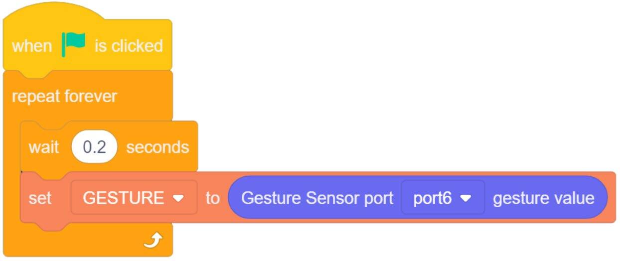
(a) This time, add the GESTURE SENSOR VALUE to a SET VARIABLE TO “GESTURE”.
(b) Place everything inside a forever loop with a small micro wait.
Download the code to the Magic Box
Practice with this group of code and record your results below
F. List all 8 gestures the sensor is capable of reading and indicate if they can be read consistently (majority of the time), inconsistently (sometimes), or rarely.
G. Does the orientation of the sensor matter?
H. Can the sensor see the gesture if it is a moving object? Move the sensor across the object instead of moving an object across the sensor… rotate the sensor… move the sensor toward an object…
I. Is this block MORE consistent, LESS consistent, or about the SAME as the other block with LEFT and RIGHT gestures?
J. Document additional observations below.
| # | Gesture | Consistency (✔ Consistent / ≈ Inconsistent / ✖ Rarely) |
|---|---|---|
| 1. | ||
| 2. | ||
| 3. | ||
| 4. | ||
| 5. | ||
| 6. | ||
| 7. | ||
| 8. |
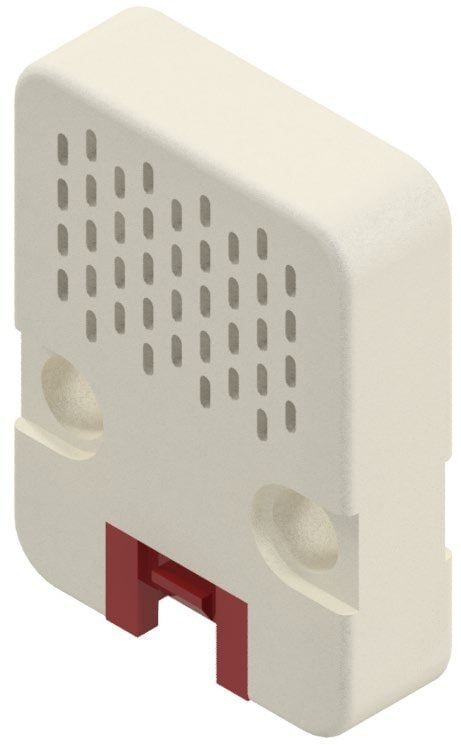
SKILL BUILDER 4 – HUMITURE SENSOR – ANALOG INPUT
1. The forth sensor this activity will explore is the HUMITURE SENSOR.
The humiture sensor is used to detect either temperature or humidity (amount of water vapor in the atmosphere) found in the current environment. It reports analog signals to the controller.
ANY GREEN PORT – PORT 1-6
2. Drag over a Humiture Intensity Value from the AI SENSOR KIT toolbox.
This one block is capable of reading either Temperature or Humidity.
3. Change the PORT value to the correct port (see page 2).
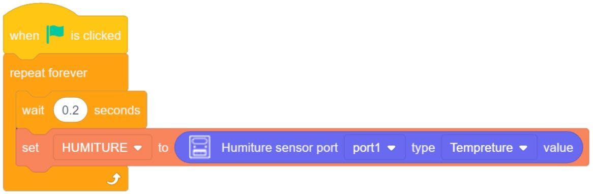
4. Create a new variable (HUMITURE) and place it inside a Set Variable loop as done in previous activities.
5. Start with the Temperature value.
6. Download the code to the Magic Box. Practice with this group of code and record your results below.

- A. What value do you get at room temperature (a default reading)?
- B. Looking at the reading you receive at room temperature, does the value make sense (F vs C… maybe…)?
- C. Try to increase and decrease the temperature. Think of creative ways to increase or decrease the temperature reading of the sensor without risk of damaging the sensor. What is Lowest and Highest you can get the sensor to read? What method do you use?
Highest Value: Method:
Lowest Value: Method:
- D. If the readings do not directly relate to something known (F or C). Can the data still be used? If so, how?
- E. Document additional observations below.
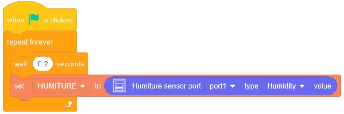
7. Change the Sensor Reading to HUMIDITY.
8. Download the code to the Magic Box. Practice with this group of code and record your results below.
- F. What default value do you get (current amount of water vapor in the air)?
- G. Try to increase and decrease the sensor reading. Think of creative ways to increase or decrease the humidity reading of the sensor without risk of damaging the sensor. What is Lowest and Highest you can get the sensor to read? What method do you use?
- H. Document additional observations below.
YES / NO HOW:
Highest Value: Method:
Lowest Value: Method:
SKILL BUILDER 5 – LIGHT SENSOR – ANALOG INPUT
1. The fifth sensor this activity will explore is the LIGHT SENSOR.
The light sensor contains a photosensitive resistor. The resistance value decreases with the increase of light intensity. Based on this, the change of its voltage is detected, and the light intensity data is obtained through AD conversion.
PORT 3 or 4
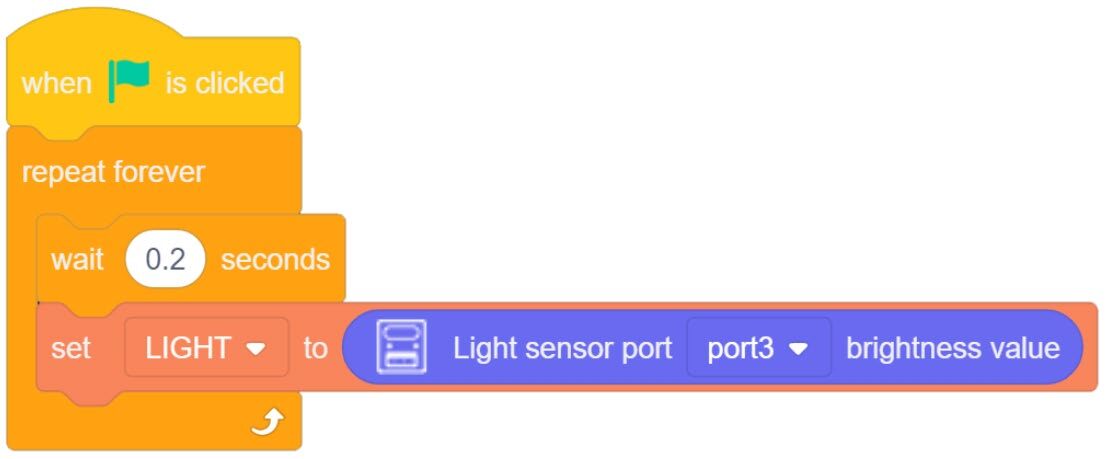
2. Drag over a Light Brightness Value from the AI SENSOR KIT toolbox.
This one block is capable of reading the brightness or intensity of the light seen in an environment.
3. Change the PORT value to the correct port (see page 2).
4. Create a new variable (LIGHT) and place it inside a Set Variable loop as done in previous activities.
5. Download the code to the Magic Box. Practice with this group of code and record your results below.

- A. What default value do you get (Amount of ambient light, no direct alteration to the amount of light in an environment)?
- B. Try to increase and decrease the sensor reading. Think of creative ways to increase or decrease the light reading of the sensor without risk of damaging the sensor. What is Lowest and Highest you can get the sensor to read? What method did you use?
- C. Do shadows have effect on the sensor readings (stand over the sensor to create a shadow)?
- D. Document additional observations below.
Highest Value: Method:
Lowest Value: Method:
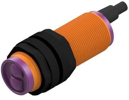
SKILL BUILDER 6 – PHOTOELECTRIC IR SENSOR – DIGITAL INPUT
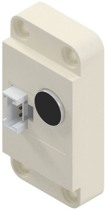
1. The sixth sensor this activity will explore is the PHOTOELECTRIC IR SENSOR.
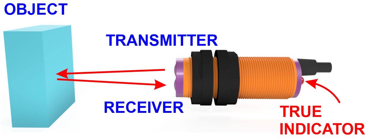
The photoelectric sensor, often called a photoelectric proximity switch, or IR sensor is a digital input. It detects the presence of an object through the connected circuit if there is an object shielding or reflecting the IR beam. The photoelectric sensor converts the input current into an optical signal on the transmitter side. The receiver side detects a target object if the transmitter signal is received by the receiver.
The detection distance can be adjusted by rotating the screw on the backside of the sensor. Rotating the screw clockwise will increase the distance.
ANY GREEN PORT – PORT 1-6
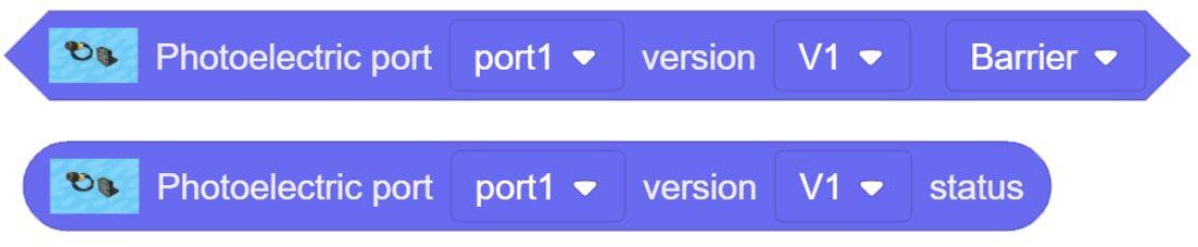
1. Drag over both Photoelectric tools from the AI SENSOR KIT toolbox.
2. Change the PORT values to the correct ports (Green 1-6) and set the VERSION to V2.
3. Create a new variable (PHOTOIR) and place it inside a Set Variable loop as done in previous activities.
4. Download the code to the Magic Box. Practice with this group of code and record your results below.
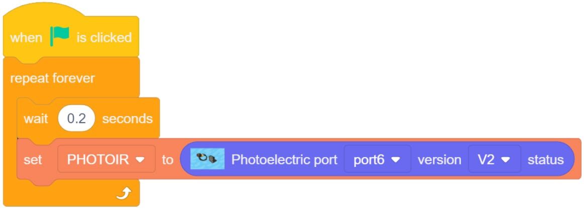
- A. What values does the variable report? If the program does not work, try to change the version number from V2 to V1.
- B. Document additional observations below.
![]() Note that there is a small red LED on the back of the sensor that lights when a signal is received. This can be used to help determine if the sensor is working properly.
Note that there is a small red LED on the back of the sensor that lights when a signal is received. This can be used to help determine if the sensor is working properly.
5. Notice from the previous test that the photoelectric sensor is a digital sensor. The last block can only report either a 1 or a 0. This new block will allow us to set the variable to report the same number values OR a string value of our choosing.
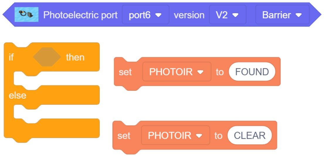
Create an IF/ELSE Statement.
A TRUE condition will change the variable PHOTOIR to FOUND.
ELSE (not true) the variable will show as CLEAR.
6. Place everything inside a forever loop with a small micro wait.
7. Download the code to the Magic Box. Practice with this group of code and record your results below.
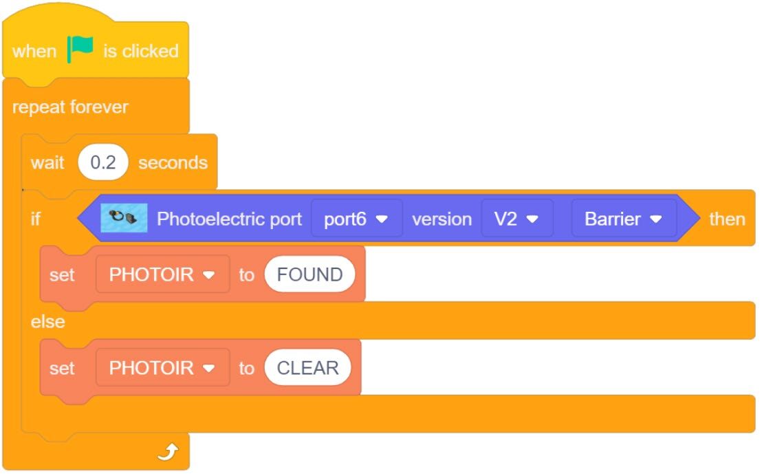
- C. Using the setting
BARRIER, what values does the variable report? - D. Using the setting
NO BARRIER, what values does the variable report? - E. What happens when you switch between the two settings?
- F. What is the terminology used for when a switch reads False by default when no signal is present? (Term was identified in a previous activity when digital inputs were introduced)
- G. What is the terminology used for when a switch reads True by default when no signal is present? (Term was identified in a previous activity when digital inputs were introduced)
- H. Document additional observations below.
What value for ON - Object Found: What value for OFF – NO Object Found:
What value for ON: What value for OFF:
What value for ON: What value for OFF:
Teaching Tips:
SECTION 4 – WIRING the MAGIC BOX AND SENSORS – SETUP #2
Caution: NEVER wire anything to the Magic Box while it has power on. ALWAYS turn it off before making connections or damage to the Controller could occur. Be sure to ask your instructor if you have any questions.
Caution: MAKE SURE THE TAB IS PRESSED DOWN ON THE WHITE CONNECTOR WHEN DISCONNECTING ALL SENSORS!!! It is very easy to damage the sensors if the white connector is pulled or tugged on without pressing down the small white tab to release the cable from the sensor housing.
CAREFULLY DISCONNECT ALL OF THE CURRENT INPUTS FROM THE MAGIC BOX
SETUP #2
3. For this part of the activity, you will need:
- 1× Magic Box
- 1× USB-A to USB-C Cable
- 1× AC/DC Power Adapter (12 V)
- 6× Common Sensor Cables
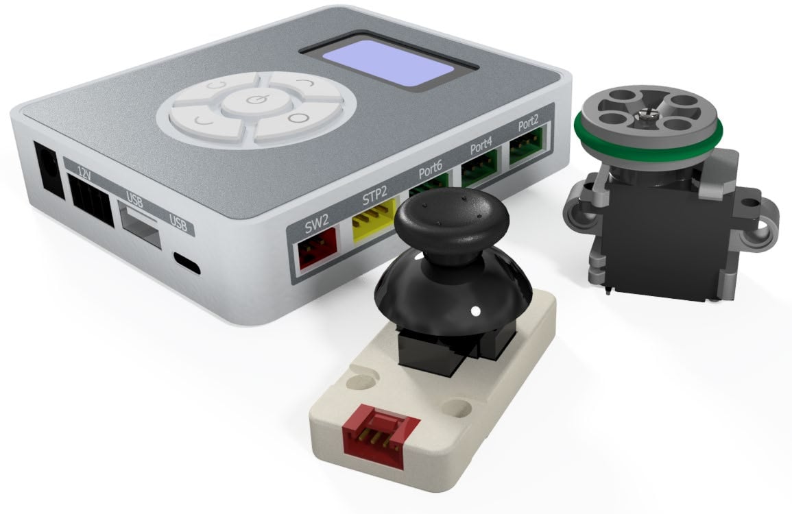
- 1× Joystick – PORT 4
- 1× Micro Servo – PORT 6
4. Wire the Magic Box as shown.
SECTION 5 – SETUP #2 - EXPLORING ADVANCED SENSORS & OUTPUTS
• JOYSTICK & MICRO SERVO
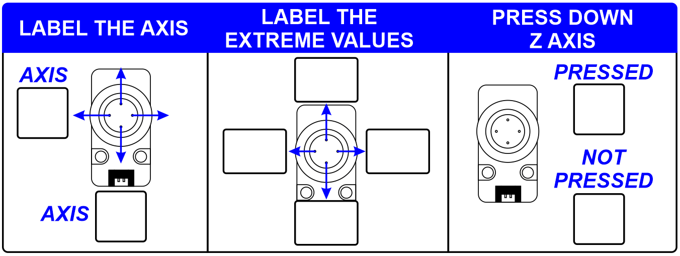
SKILL BUILDER 7 – JOYSTICK – ANALOG/DIGITAL INPUT
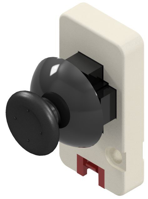
1. The sixth sensor this activity will explore is the Joystick.
The working principle of the joystick is similar to that of a general gamepad joystick. The X and Y axis correspond to two 10 kΩ potentiometers respectively. When the joystick moves, it generates a corresponding analog signal and outputs the offset value. The Z-axis acts as a button (momentary digital signal).
ANY GREEN PORT – PORT 1-6
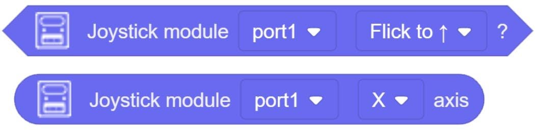
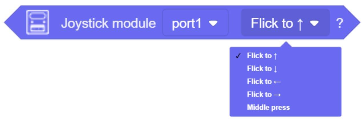
2. Drag over the two blocks for the joystick Value from the AI SENSOR KIT toolbox.
3. Change the PORT values to the correct ports (Green 1-6).
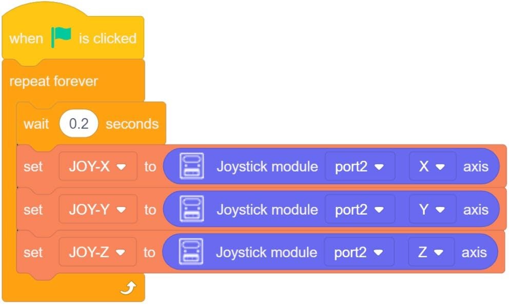
4. Create three new variables (JOY-X), (JOY-Y), (JOY-Z) and place them inside Set Variable loops as done in previous activities.
5. Download the code to the Magic Box. Practice with this group of code and record your results below.
A. Fill in the chart below.
- Which axis is the Y and which is the Z.
- Push the joystick to its four limits & document the extreme values (lowest or highest value reported).
- Press down on the joystick, what values are reported when it is pressed and not pressed.
8. The conditional block allows a programmer to create statements that can perform various operations when each motion is detected (disregarding the amount of motion).
SKILL BUILDER 8 – MICRO SERVO - OUTPUT
1. This device is the only output used in these experiments.
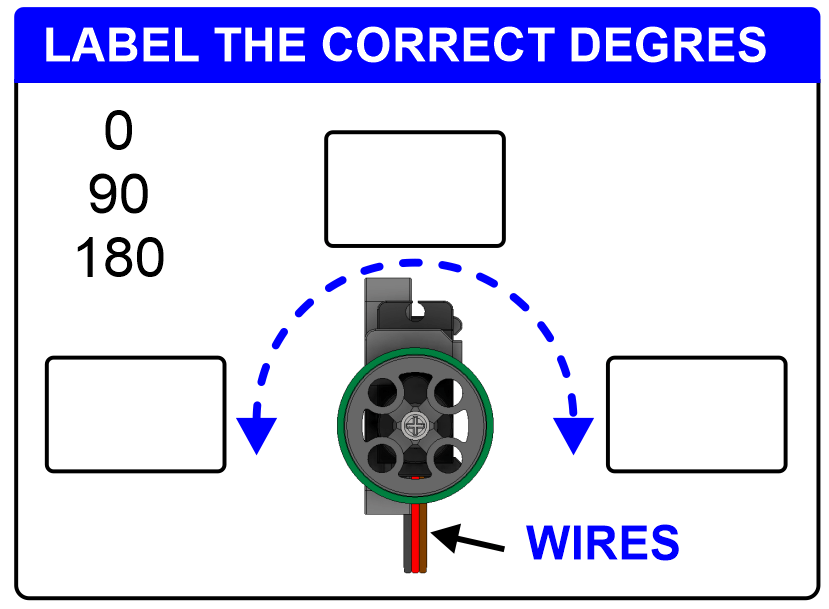
The servo acts as a motor that can be accurately positioned between 0 and 180 degrees. The position can be held indefinitely and is controlled by an internal potentiometer. The servo runs at a constant speed.
PORT 3-6

2. Drag over the Set servo angle block from the AI SENSOR KIT toolbox. This block allows the programmer to drive the servo to a specific location and hold that position.
3. Change the PORT values to the correct ports (Green Ports 3-6).
4. Create the simple program to the right.
5. Download the code to the Magic Box. Practice with this group of code and record your results below.

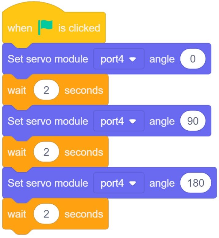
A. Hold the servo in the orientation shown to the right. After running the program, fill in the servo positions (0, 90, 180).
Teaching Tips:
CHALLENGE
SECTION 6 – USE the JOYSTICK TO CONTROL THE SERVO
1. Use the joystick to control the position of the servo.
- If the joystick is pushed left, the servo will turn CCW (to the left) to its extreme degree and stay there.
- If the Joystick is pushed right, the servo will turn CW (to the right) to its extreme degree and stay there.
- If the joystick is pressed down, the servo will center itself and stay there.
- This process will repeat forever.
Notes/Observations:
CONCLUSION
Each sensor has its own conclusion questions built in. Answer the questions above for each section and get your instructor’s approval.
GOING BEYOND
Finished early? Try some of the actions below. When finished, show your instructor and have them initial on the line.
- _________ Use the joystick’s analog values to control the position of the servo.
- _________ Scenario: Wave your hand to the right and the robot looks right. Wave your hand to the left and the robot looks left. Use the gesture sensor to control the position of the servo.
- _________ Scenario: Nighttime, the windows close. Daytime the windows open. Use the light sensor to control the servo. If the light is low, the servo will turn to one extreme. If the light is high, the servo will turn to the opposite extreme.
- _________ Scenario: Swipe your hand right, and the robot picks up a block from a common position and places it on a pallet to the right. If you swipe your hand left, it will pick up the block from the common position and place it on the left pallet. The robot will wait for a hand swipe.