Lesson Modules
Teaching Tips:
Caution: NEVER wire anything to the Dobot Magician while it has power on. ALWAYS turn it off before making connections or damage to the robot could occur.
1. Typical Start Up Procedure
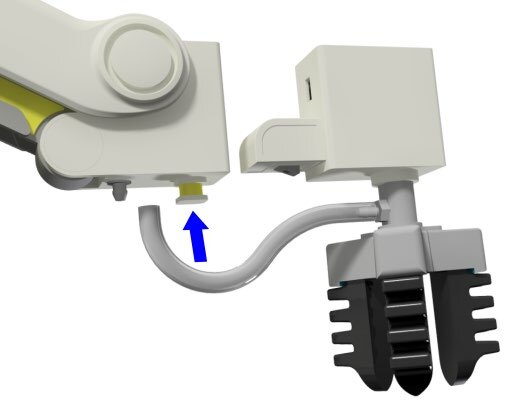
- Disconnect any existing END of ARM TOOLING (EoAT).
- Carefully disconnect any existing vacuum tubes.
- Press and hold the release button on the bottom of the arm and pull off the EoAT.
- Attach the Pen holder as the END EFFECTOR or END of ARM TOOLING (EoAT) on the Dobot.
- Push the pen holder in until it snaps in.
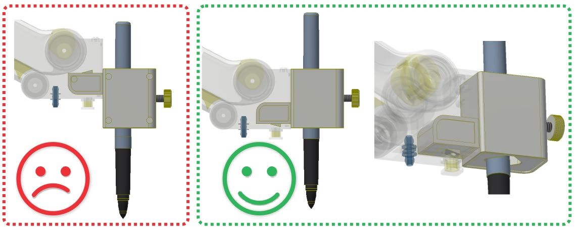
![]() Do not try to attach the pen holder upside down. The locking tab should be on the bottom.
Do not try to attach the pen holder upside down. The locking tab should be on the bottom.
- Plug the 120-240 VAC power into an outlet.
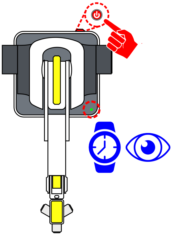
- Attach the 12 V DC 5 A barrel plug of the power supply and USB to the Dobot. Plug the USB into the computer and wait for a connection. WATCH and WAIT for the robot to completely power on (GREEN INDICATOR).
- Turn on the power to the Dobot (Robot will beep when ready).
- Open DobotLab software.
2. Once the Robot’s USB is connected to the computer and the robot is powered on, open the DobotLab software


3. Once the software is opened select the Teaching and Playback Lab.
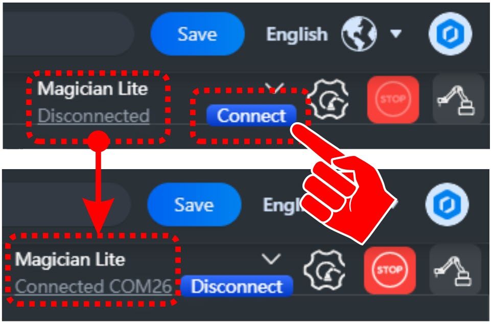
4. Select Connect to establish control from the software to the robot. “Disconnected” should change to “Connected” and show the COM being used (COM is the USB port being used by the robot)
5. NOTE: If no robot is found, the prompt will show as Searching…
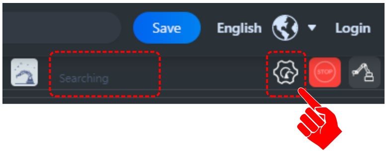
SEARCHING… Complete the steps below if no robot is found.
Select the Gear Icon next to the Force Stop Icon.
Make sure the hardware you are connected is checked.
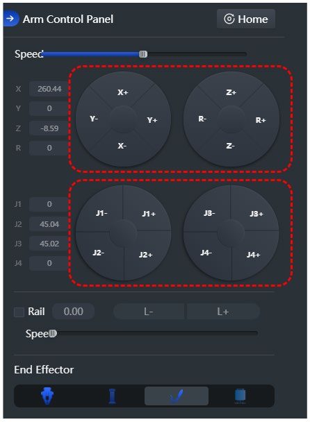
ARM CONTROL PANEL
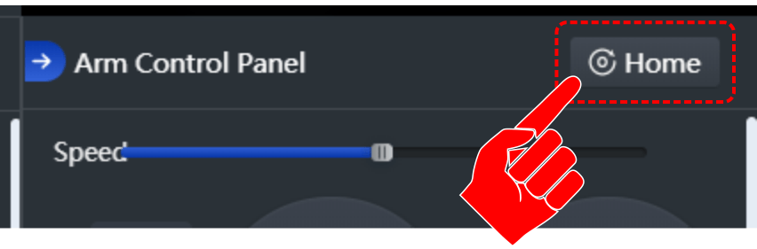
6. Select the ARM CONTROL Icon to open the arm control panel.
Before HOMING the robot, make sure the robot’s WORK ENVELOPE, the area in which the robot can reach, is clear.

7. Select the HOME icon to start the robot’s homing process. Homing the robot will return the robot to its initial HOME position.
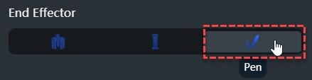
8. Be sure the Pen is chosen as the Dobot’s END EFFECTOR or EoAT (End of Arm Tooling).
9. Insert a ball-point pen or marker into the holder replacing the one that is there and remember to remove the cap.
ARM CONTROL PANEL
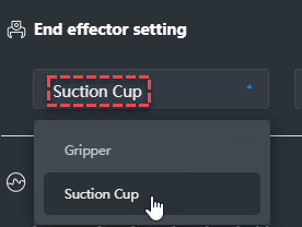
10. In the CONTROL PANEL, set the end effector as the suction cup (the pen is not an option to select).
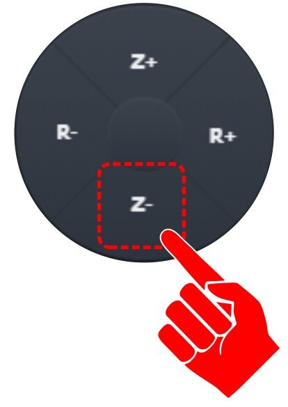
11. Use the Axis and Joint buttons to move the robot around. Using the diagram below, identify the AXIS MOVEMENT and JOINT MOVEMENTS for the robot (1-14). Be sure to label them as +/-. (Press and hold ALL 16 options, what they do, left or right, up or down, in or out...)
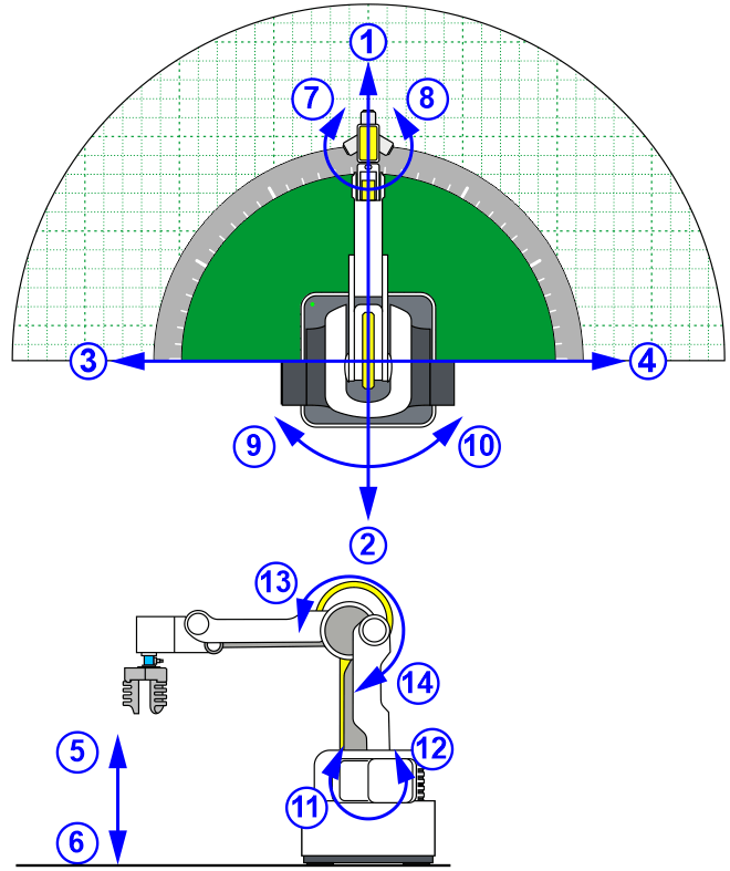
12. Using the information you documented on the previous diagaram, write down the correct axis/joint button in the first empty column, and a description of what it does in the second.
| AXIS / JOINT + / - | DESCRIPTION IN / OUT / UP / DN / LEFT / RIGHT |
|---|---|
| 1 Axis | |
| 2 Axis | |
| 3 Axis | |
| 4 Axis | |
| 5 Axis | |
| 6 Axis | |
| 7 Wrist | |
| 8 Wrist | |
| 9 Waist | |
| 10 Waist | |
| 11 Shoulder | |
| 12 Shoulder | |
| 13 Elbow | |
| 14 Elbow |
13. Did the axis button work as you expected… did it move the way you thought it would? Explain:
14. How do the XYZ movements differ from the J movements?
Teaching Tips:
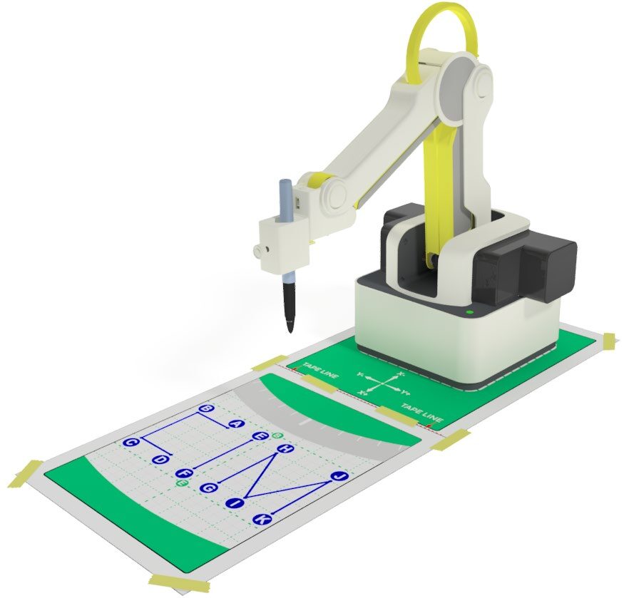
15. MAIN OBJECTIVE:
- A. Tape together the two parts of the Template along the RED TAPE LINE.
- B. Tape the Template to the table.
- C. Place the Robot on the Template.
- D. Handwrite the word “CIM” in pencil on the Dobot Template as shown.
- E. Using the Dobot Lite with the pen end effector, start at point A on your diagram and move the robot from point to point to re-write the word using straight lines. Be sure to pick up the pen between letters.
- F. Send the robot to a home position away from the paper when finished.

16. What do you think is this the best way to write the letters CIM (order of movement)? Did you take time into consideration? How?
![]() When moving in the z-axis, try to put a light pressure on it when you write, or it may tear the paper or break the tip. The pen is NOT spring-loaded; You have to have a soft touch or the paper may tear or the pen may be caught on the paper and slide the robot’s base. It may be a good idea to put a piece of cardboard under the paper to give it a softer surface to write on.
When moving in the z-axis, try to put a light pressure on it when you write, or it may tear the paper or break the tip. The pen is NOT spring-loaded; You have to have a soft touch or the paper may tear or the pen may be caught on the paper and slide the robot’s base. It may be a good idea to put a piece of cardboard under the paper to give it a softer surface to write on.
17. For this activity, we will use a combination of recorded and taught positions…
The big GREEN squares on the paper are equal to about 20 mm; this will help us plan our letters.
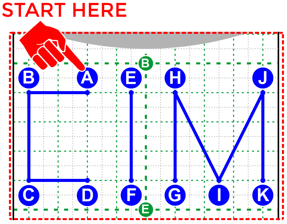
18. Line Segment lengths are as follows:
AB = 40 mm BC = 60 mm CD = 40 mm EF = 60 mm GH = 40 mm *HI = 68 mm *IJ = 68 mm JK = 60 mm
19. Make sure you are in the Teach and Playback lab.
- We will use this lab to RECORD and TEACH the robot the points we want it to go to write the word CIM. There are two methods to RECORDING a point.
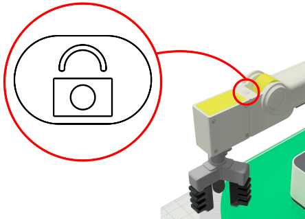
Method 1: RECORDED points can be found using the unlock button on the robot’s arm. When the unlock button is pressed, the arm becomes free to manually move to a new location. The location is automatically RECORDED and added as a step in the program when the unlock is released. Movements in between the steps (while the button is held) will not be recorded.
Method 2: RECORDED points can also be found by manually driving the robot to a position from the Arm Control Panel and selecting Save Point when the EoAT is at the desired location

TEACHING points is the process of manually typing in the XYZ coordinates if they are known. We often use this method to TOUCH UP points (round them to whole numbers, change them to a known number, or duplicate positions from previous steps that should not have changed). )
![]() Always start a program with a safe/clear HOME position. Home is a position that is up and away or clear of any obstacles.
Always start a program with a safe/clear HOME position. Home is a position that is up and away or clear of any obstacles.
20. Using the XYZ buttons on the Arm Control Panel, move the robot to a safe HOME position. We can refer to this as "HOME".
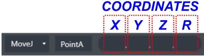
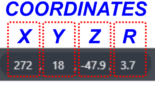
-Touch up (round) the coordinates as needed. Ignore the last number in the coordinate’s window “R”, as this stands for “rotation or roll”. It is not used with the pen.

Example: Move the robot above the template and check the alignment before recording the next point.
-Record these values on the chart below.
Using the XYZ buttons on the Arm Control Panel, move the robot to a point above POINT A. We can refer to this as AB-A (Above Point A). Do not touch the paper yet with the pen! Record this value on the chart below.
21. You can also press the “Lock” button on the arm and it will RECORD the point where the pen is when the button is released…
Record the values to create the letter CIM on the chart below.
| STEP | POSITIONS | X = | Y = | Z = |
|---|---|---|---|---|
| 1 | HOME | |||
| 2 | AB-A | |||
| 3 | AT-A | |||
| 4 | AT-B | |||
| 5 | AT-C | |||
| 6 | AT-D | |||
| 7 | AB-D | |||
| 8 | AB-E | |||
| 9 | AT-E | |||
| 10 | AT-F | |||
| 11 | AB-F | |||
| 12 | AB-G | |||
| 13 | AT-G | |||
| 14 | AT-H | |||
| 15 | AT-I | |||
| 16 | AT-J | |||
| 17 | AT-K | |||
| 18 | AB-K | |||
| 19 | HOME |
Click in the cell with the “P” for each point to create a descriptive name for each position. See Example Below “AT-A” (EoAT is At Point A).

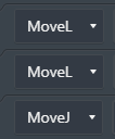
![]() Movements can either be MoveJ, MoveL, or Jump. We will get to Jump in later activities. MoveJ movements always have an arc to them. We use them for movements that can have less accuracy. Example: when traveling from home to an above position or when traveling from an above to another above position. MoveL movements are linear. We use them when moving down to a point or object, or when moving away from a point or object to ensure movement accuracy. All of the lines to create the letters for CIM should use MoveL movements
Movements can either be MoveJ, MoveL, or Jump. We will get to Jump in later activities. MoveJ movements always have an arc to them. We use them for movements that can have less accuracy. Example: when traveling from home to an above position or when traveling from an above to another above position. MoveL movements are linear. We use them when moving down to a point or object, or when moving away from a point or object to ensure movement accuracy. All of the lines to create the letters for CIM should use MoveL movements
If TEACHING the positions, select the Save Point tool to create 19 empty steps. Using the chart you created, fill in the names of the steps and the XYZ values.
Note: The coordinates automatically used for the Save Point is the current location of the EoAT
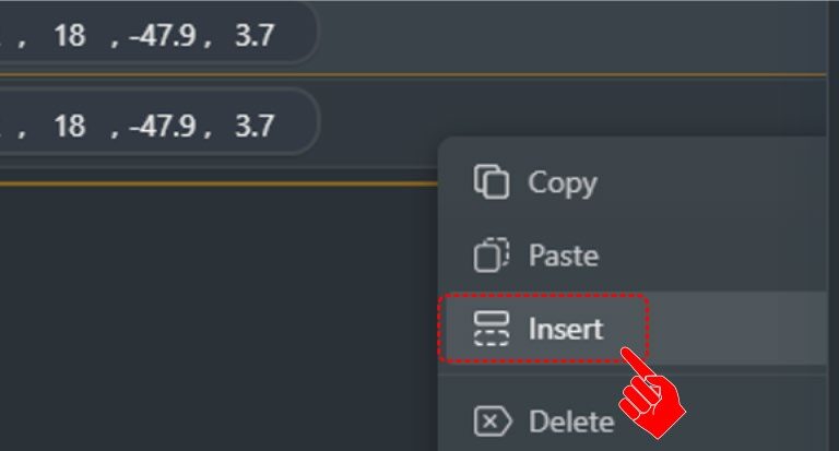
You may also right click on an existing step and select insert to create an additional step

If RECORDING the positions, the positions are automatically created as well as filled in. These positions should be touched up.
Touch Up Example 1: AB (Above) positions should only have a different Z value. The X and Y should be the same.
Touch Up Example 2: All AB (Above) positions should have the same Z value. All AT (At) positions should have the same Z value.
Touch Up Example 3: The positions for AT-A and AT-B should only change on one axis.
22. Change the Motion Styles to MOVEJ and MOVL where appropriate.
23. It is beneficial to step through (run one line of code at a time) a program to find any errors…
If there are errors in a step, update the XYZ coordinate values until they are correct. Repeat this process for each step.

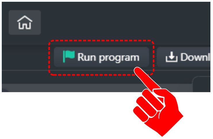
24. Once each individual step is verified, run the entire program. Select the first line of code, ensure there are no obstructions in the robots path, and select the RUN PROGRAM option at the top of the screen.
25. Now that we know all the points are correct, we must change the Z value so that it writes on the paper. To do this, follow these steps:
-
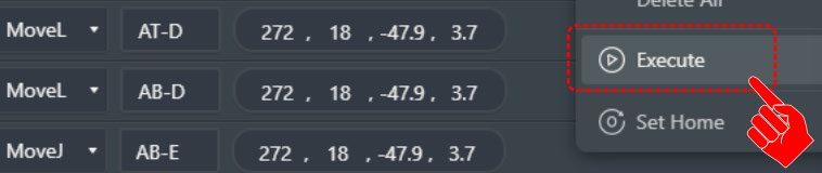
A. Select the first AT line, right-click & “Execute” to move the robot to point A.
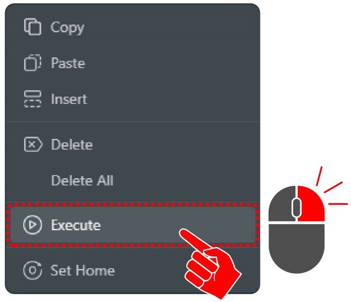
-
B. Change the Z by increasing its value −2 mm at a time and hitting Run Selected until the pen just touches the paper.
-
C. Change all Z values where the pen must write; leave AB positions alone when moving letter-to-letter.
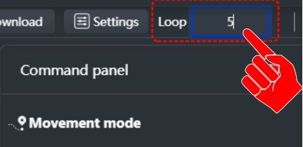
26. Using the Loop button, change it to 5 and watch your program LOOP five times when you hit the start button.
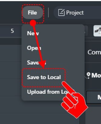
Save your work. Select File → Save to Local to save your project on the computer.
Let’s check the ACCURACY & REPEATABILITY of our robot. Get another grid portion of the template—either replace the old one or add it on top. Tape it down, run the program again, then answer:
How accurate and repeatable was your robot and program? Be sure to describe both terms.
What happens to ACCURACY & REPEATABILITY if you increase speed to 75? Try it and see.
![]() (Do not exceed the speed specified by your instructor.)
(Do not exceed the speed specified by your instructor.)
![]() To change the speed, select the Settings tab at the top of the screen.
To change the speed, select the Settings tab at the top of the screen.

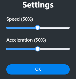
Speed Adjustment: What happened when you changed the speed? Be specific.
Teaching Tips:
CONCLUSION
- What does it mean to touch up a program?
- Explain completely the difference between MOVJ and MOVL Motion Styles.
- Does speed influence ACCURACY or REPEATABILITY of your robot? Describe how.
- What would be the effect on the robot’s accuracy at higher speeds if you greatly increased the mass of the pen?
- After completing this activity, how would you define the difference between a robot’s accuracy versus its repeatability?
- Why do we use AB (Above) positions before going to AT (At) positions? Explain fully.
- What is the purpose of a HOME position?
GOING BEYOND
Finished early? Try drawing one of the options below. When finished, show your instructor and have them initial on the line.
- Teach the robot to make a barcode with the pen.
- Teach the robot to write your name.
- Teach the robot to write arcs (can you figure Arc movements out?).
Teacher Signature
________ 1. Teach the robot to make a barcode with the pen.
________ 2. Teach the robot to write your name.
________ 3. Teach the robot to write arcs (can you figure Arc movements out?).