Lesson Modules
Teaching Tips:
PROCEDURE
SECTION 1 – INSTALLING THE ROBOT ON THE LINEAR SLIDE RAIL
![]() If this section is already complete, skip to SECTION 2 – WIRING.
If this section is already complete, skip to SECTION 2 – WIRING.
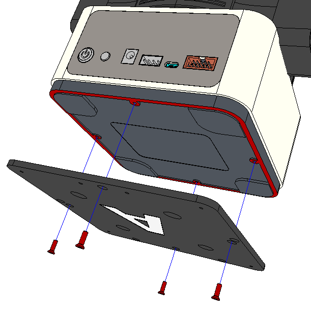
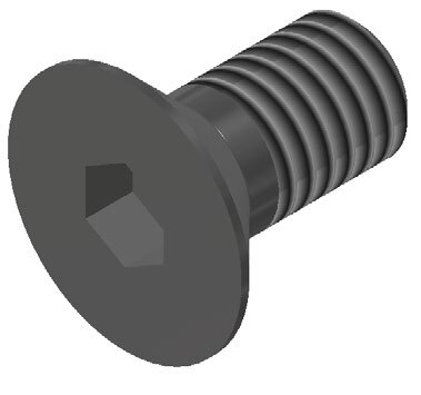
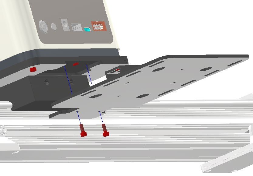
Step 1 – Mount the Dobot Magician on PLATE A
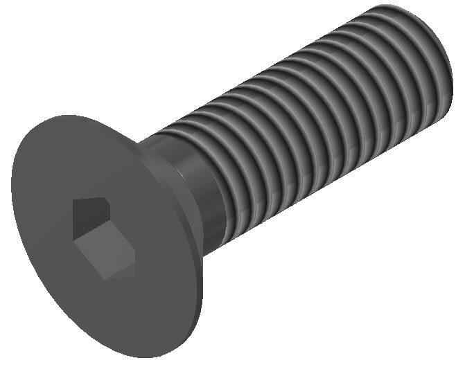
Mount the Dobot Magician on PLATE A with FOUR M3x10 countersink cap screws. Ensure the countersinks of PLATE A point outward. Orient the plate as shown in the image to the right.

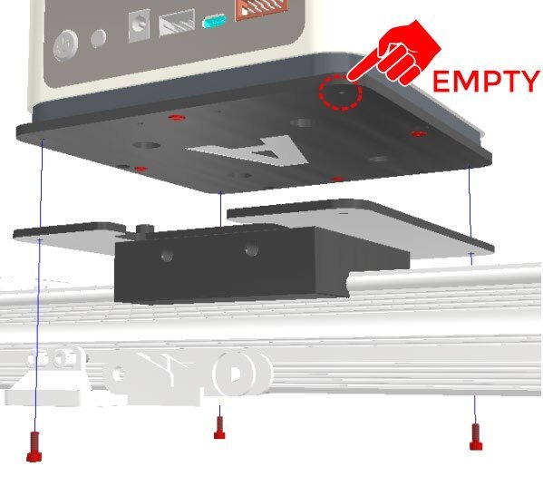
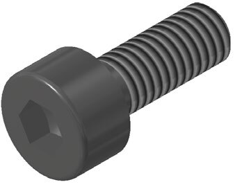
Step 2 – Mount PLATE A onto PLATE B
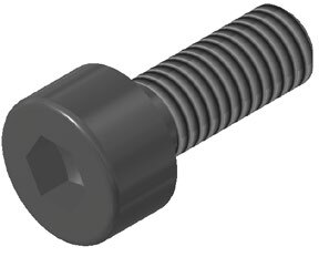
Mount PLATE A (with the Dobot Magician attached) onto PLATE B with THREE M3x8 Hex-Socket Head Cap Screws. Make sure the back of the robot faces the cut out on the back of PLATE B.
![]() Do not put a screw in the back right corner (EMPTY). We need this hole for the next step
Do not put a screw in the back right corner (EMPTY). We need this hole for the next step

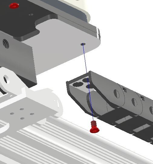
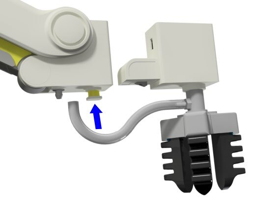
Step 3 – Connect the WIRE DUCT
Connect the free end of the WIRE DUCT to PLATE B with ONE M3x6 Countersink screw.

Step 4 – Attach PLATE C
For this activity, in order for use with the Magic Box we will need PLATE C to carry it. Attach PLATE C onto PLATE A with TWO M3x8 Hex-Socket Head Cap Screws.


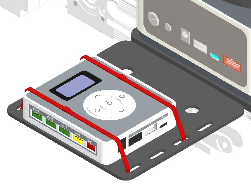
Step 5 – Secure the VACUUM PUMP
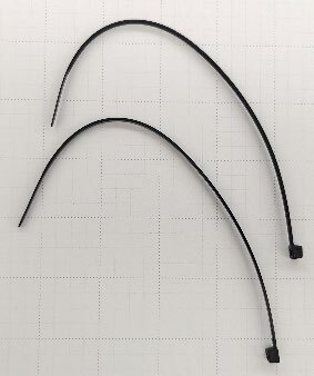
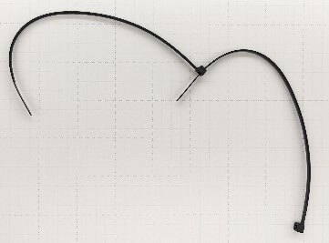
Use the included ZIP-TIES to attach the VACUUM PUMP to PLATE C. It may be necessary to link/chain more than one zip tie in order to make a complete loop around the Magic Box and bracket.
SECTION 2 – WIRING THE ROBOT & LINEAR SLIDE RAIL
![]() If this section is already complete, skip to SECTION 3 – SETUP & PROGRAMMING.
If this section is already complete, skip to SECTION 3 – SETUP & PROGRAMMING.
Step 1 – Connect the slide rail wires
Connect the four wires from the linear slide rail to the back of the MAGIC BOX. The wires should reach from the wire duct to the MAGIC BOX.
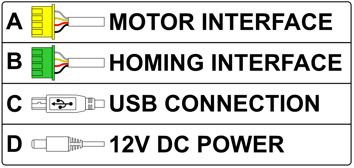
GREEN – PORT 4 USB-B to CONVERTER (Convert to USB-C) to Magic Box
YELLOW – STP 2 12V SHARED POWER to Magic Box
(A) – The motor interface controls the direction and location of the stepper motor
(B) The homing cable is attached to the limit switch at the end of the conveyor and reports when the slide base has been homed to a zero location.
(C) - The USB connection is an extension cable routed through the wire duct and allows the robot to communicate directly with the computer.
(D) - The 12V DC cable powers both the robot and the linear slide base .
Teaching Tips:
SECTION 3 – SETTING UP & PROGRAMMING THE ROBOT & LINEAR SLIDE RAIL
Caution: NEVER wire anything to the Dobot Magician or Magic Box while it has power on. ALWAYS turn it off before making connections or damage to the robot could occur. Be sure to ask your instructor if you have any questions.
1. Typical Start Up Procedure
- Disconnect any existing END of ARM TOOLING (EoAT).
- Carefully disconnect any existing vacuum tubes.
- Press and hold the release button on the bottom of the arm and pull off the EoAT.
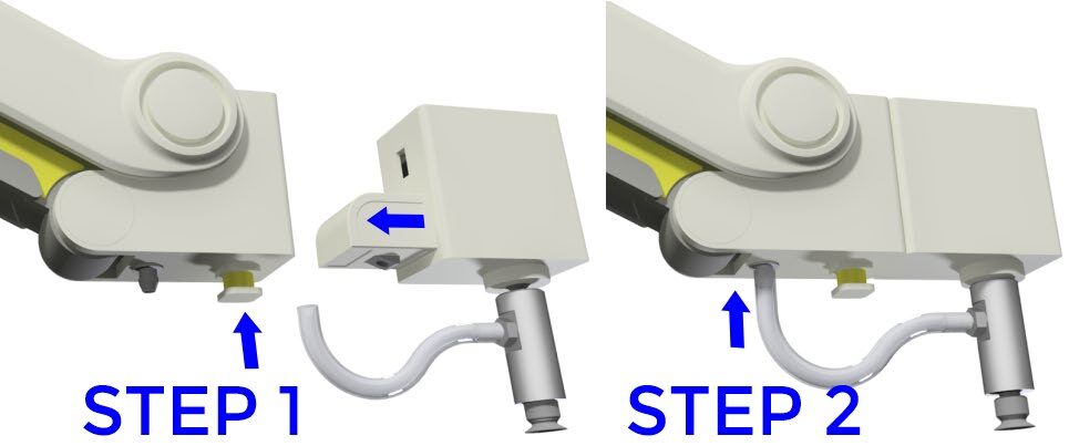
2. Attach the Suction Cup
Attach the Suction Cup as the END EFFECTOR or END of ARM TOOLING (EoAT) on both robots.
- STEP 1 – Push the Suction Cup in until it snaps in place.
- STEP 2 – Attach the hose to the air nozzle.
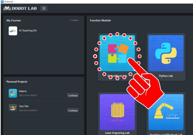
3. Open DobotBlock Lab
Open up DobotBlock Lab in the software and connect the robot.


4. Open a new file for DobotBlock Lab
![]() Turn on the power to the Magic Box. The Magician Lite will automatically power up.
Turn on the power to the Magic Box. The Magician Lite will automatically power up.
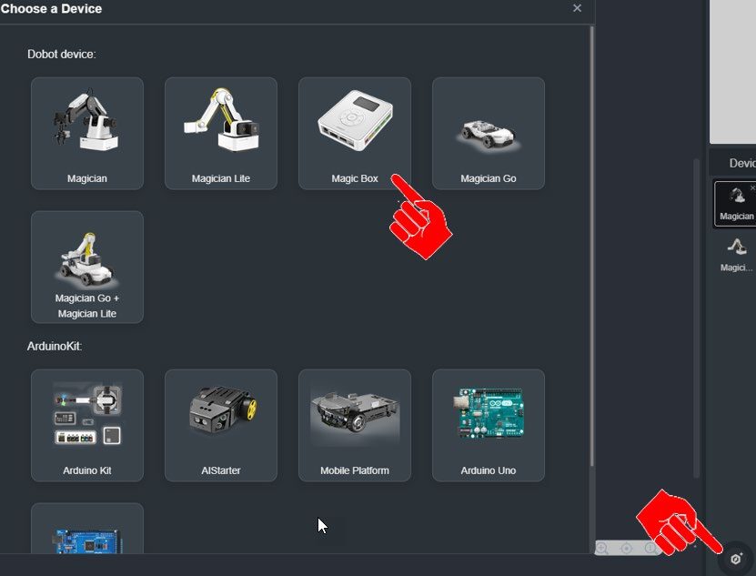
5. Add a Magic Box to Devices
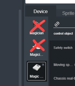
6. Delete unnecessary devices
Under Devices, delete the Magician and Magician Lite.
7. Add the EXTENSION
For this activity, we will need to add the EXTENSION to use the Magician Lite. Click the EXTEND icon in the bottom left corner.
8. Select the Magician Lite Extension
Select Extend, then Select the Magician Lite Extension


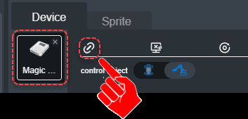
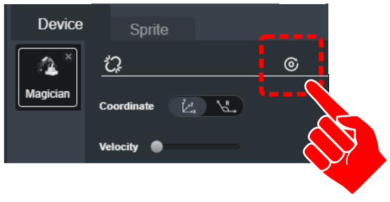
9. Connect the Magic Box
Select the connect icon to establish control from the software to the Magic Box. A connection window should pop up.
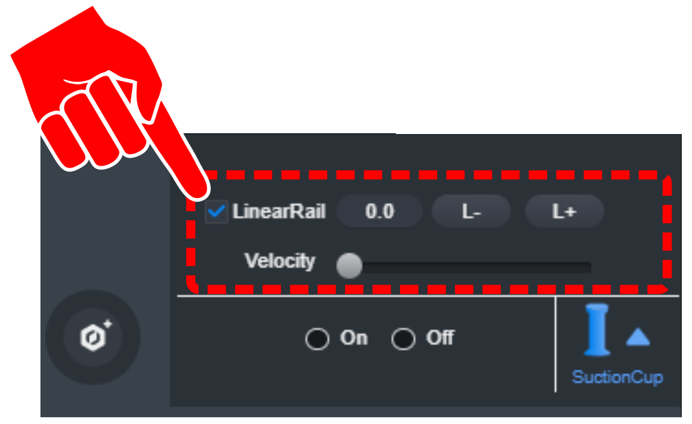
10. Home the slide & robot
Select the CHECK box for the LinearRail BEFORE homing the robot.
11. Clear the area and home
ENSURE THE AREA IS CLEAR OF OBSTRUCTIONS & LIMIT SWITCH CABLE IS CONNECTED ON BOTH ENDS. When the home icon is selected, the Linear Slide Base will slide all the way to the limit switch (End with the stepper motor). The robot will home after the slide base has homed.
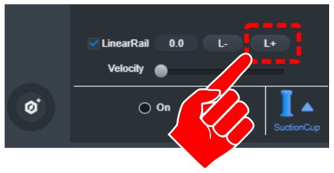
12. Test the slide movement
Once the Linear Slide Base and Robot are homed, select the L+ icon. The robot should slide away from the stepper motor. The value shown is not actually the distance traveled. Since the motor is a stepper motor, the number shown is a position that the slide base has traveled too.
DO NOT ADJUST THE VELOCITY SLIDER!
13. Add the COLOR SENSOR extension
For this activity, we will need to add an EXTENSION to use the COLOR SENSOR. Click the EXTEND icon in the bottom left corner.

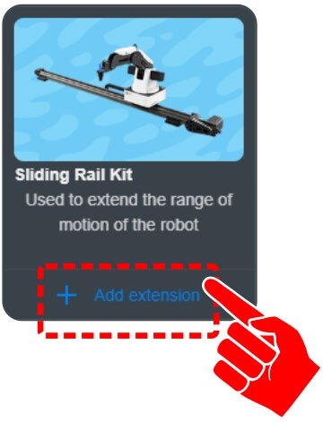
14. Add extension for the Sliding Rail Kit
Click on “+ Add extension” for the Sliding Rail Kit.
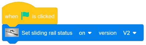
15. Set the rail status
The first step in programming this activity is to set the status of the rail.
- V1 – RED Bumpers at the end of each rail
- V2 – BLUE Bumpers at the end of each rail
At this time do not use the Set Velocity Block
Sliding Rail Extended Toolbox:
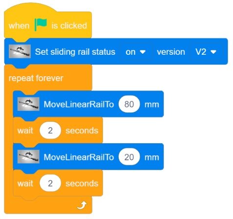
– Set Sliding Rail Status “ON” & “V2”
16. Create a test program
Create a simple test program that will send the robot out to location 80 mm, wait for 2 seconds, travel back to location 20 mm, wait for 2 seconds, and then repeat the loop.
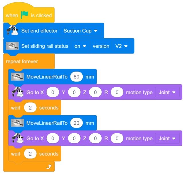
17. Add movements at 80 mm and 20 mm
Add a movement after the robot has reached the 80 mm and a different movement at 20 mm.
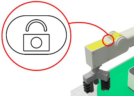
![]() Use the Unlock Arm Control to Grab new locations (any new positions will do for this test) and Fill those Coordinates into the Go To Commands
Use the Unlock Arm Control to Grab new locations (any new positions will do for this test) and Fill those Coordinates into the Go To Commands
SECTION 4 – PICK AND PLACE USING THE LINEAR SLIDE BASE
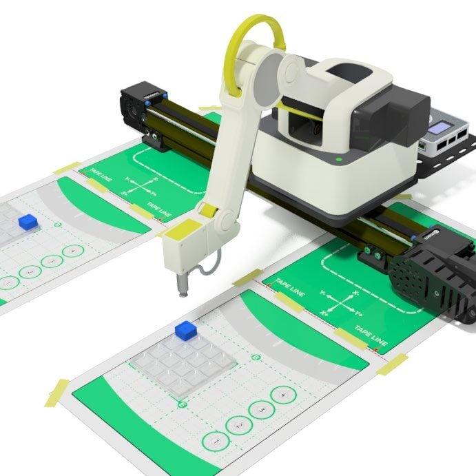
- Tape both field diagrams to the table as shown below (one towards each end of the slide base. See your instructor for specific locations) *NOTE: the slide base shown has been reduced in length
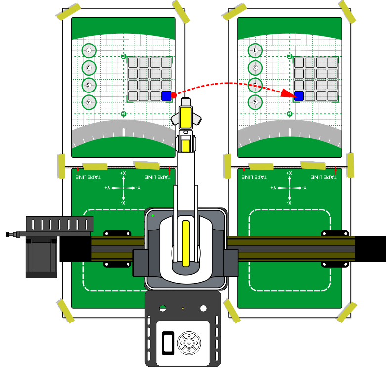
- Tape both field diagrams to the table as shown.
- Create a pick and place activity that will move a block from one field diagram to the other. Get the starting and ending locations from your instructor.
Teaching Tips:
CONCLUSION
- Find a video example of a working sliding base being used in industry. Explain what operation it is doing.
- How is the slidebase in question #1 similar to the one you are using?
- How is the slidebase in question #1 different from the one you are using?
- What was the most difficult part of this activity for you? Why? Explain fully.
GOING BEYOND
Finished early? Try some of the actions below. When finished, show your instructor and have them initial on the line.
- _________ Move a pallet of 4 blocks from one pallet to the other.
- _________ Set up the robot to “tend a machine”. Use a cardboard box for the machine at one end of the slide, a switch for the machine on/off, a field diagram for the pallet at the other end of the slide, and a cube or cylinder for the part.
- Pick a part off the Pallet
- Place a part in the machine (Box)
- Move the robot out of the machine
- When the machine is done (press the switch)
- Have the robot get the part out of the machine and return it to the pallet at the other end of the slide
If your set up did not work correctly the first time, what did you have to do to make it work?