Lesson Modules
Teaching Tips:
PROCEDURE
SECTION 1 – WIRING the MAGIC BOX, SENSORS, & MAGICIAN ROBOT
Caution: NEVER wire anything to the Magic Box or Magician while it has power on. ALWAYS turn them off before making connections or damage to the Controllers could occur. Be sure to ask your instructor if you have any questions.
1. For this activity, you will need:
- • 1x Magic Box
- • 1x USB-A to USB-C Cable
- • 1x AC/DC Power Adapter (12V)
- • 3x Common Sensor Cables
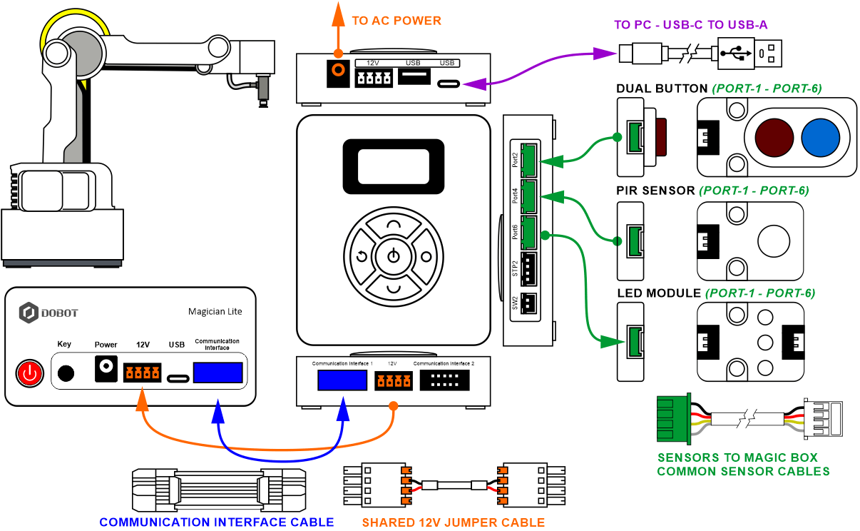
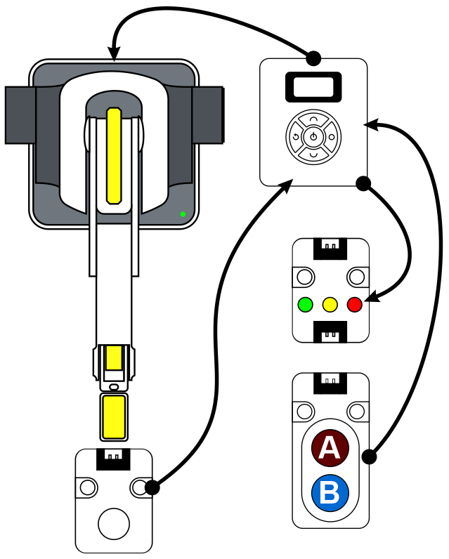
2. Wire the Magic Box as shown below
- • 1x DUAL BUTTON – PORT 2
- • 1x PIR SENSOR – PORT 4
- • 1x LED MODULE – PORT 6
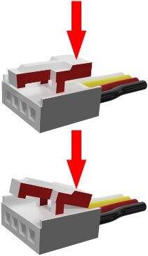
Caution: MAKE SURE THE TAB IS PRESSED DOWN ON THE WHITE CONNECTOR WHEN DISCONNECTING ALL SENSORS!!! It is very easy to damage the sensors if the white connector is pulled or tugged on without pressing down the small white tab to release the cable from the sensor housing.
SECTION 2 – CONNECTING the MAGIC BOX & ROBOT to DOBOTLAB
- Open up DobotBlock Lab in the software.


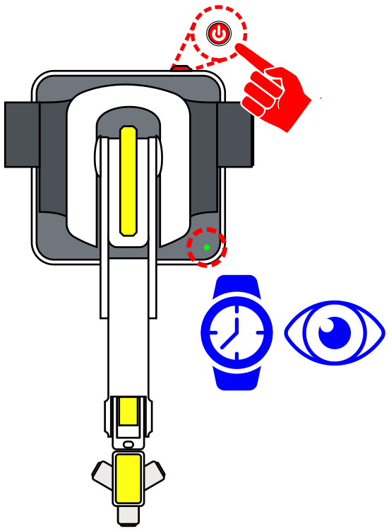
- Once ALL the wiring is done (sensors connected and robot arm connected), power ON the Magic Box and Robot. WATCH and WAIT for the robot to completely power on. (GREEN INDICATOR)

- Repeat the connection process completed in previous activities.
a) Connect to the Magic Box in DobotLab.
b) Add the AI Sensor Kit and Magician Extensions.
c) Ensure the robot’s envelope is clear and home the robot.
CHALLENGE
SECTION 3 – CREATE A STACK LIGHT PROGRAM
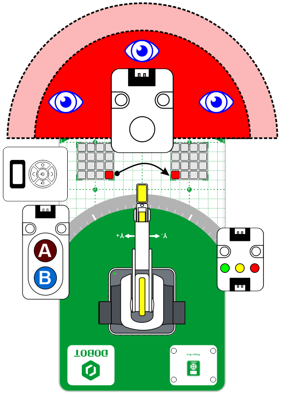
For this challenge, develop a pick and place routine that adds:
- a) A push button (B-BLUE) to start each complete loop (block in place)
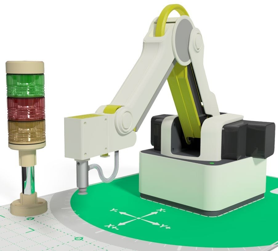
- b) A stack light for visual feedback
- • GREEN ONLY - Normal Operation - Moving
- • GREEN & YELLOW Waiting for Block (B-BLUE Push Button)
- • RED ONLY – Motion detected while in operation
- c) A PIR sensor that detects movement around the work cell environment that stops the primary operation (only while in operation)
- d) A push button (A-RED) to restart the process from warning
![]() At this time, using Blockly, a code does not exist that will stop motion once it has been started (GO TO or JUMP). For this simulation, the program will only look for motion (from the PIR) inside the work envelope in-between each motion. This is an excellent opportunity to develop a MY BLOCK that can be placed throughout the program.
At this time, using Blockly, a code does not exist that will stop motion once it has been started (GO TO or JUMP). For this simulation, the program will only look for motion (from the PIR) inside the work envelope in-between each motion. This is an excellent opportunity to develop a MY BLOCK that can be placed throughout the program.
THINGS TO THINK ABOUT:
- • What variables would be helpful? (both to simplify the program but also to debug it if it is not working as planned)
- • What MY BLOCKS would be helpful? (break up the program into sections… waiting?)
- • Use of JUMPS to cut down on motion blocks… but… does that take away the places to insert “look for motion”?
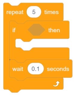
- • Possibly try something like the code below to try to catch motion? 5x 0.1 = 0.5 … half a second?
If your set up did not work correctly the first time, what did you have to do to make it work?
Teaching Tips:
CONCLUSION
- Why was the program unable to stop the robot while it was in motion?
- What other sensors/inputs from the kit could be used to add safety in a manufacturing cell, and how would they be used?
GOING BEYOND
Finished early? Try some of the actions below. When finished, show your instructor and have them initial on the line.
- _________ 1. Add the servo as an output in the work envelope to simulate dropping a safety shield while the robot is in motion.
- _________ 2. Replace the 2-Button Input module with the gesture sensor. Make “swipe left” do blue button, and “swipe right” do red button.