Lesson Modules
Teaching Tips:
SECTION 1 – WIRING the MAGIC BOX AND SENSORS
Caution: NEVER wire anything to the Magic Box while it has power on. ALWAYS shutdown the BOX before making connections or damage to the controller could occur. Be sure to ask your instructor if you have any questions.
Step 1 – Gather Components
For this activity, you will need:
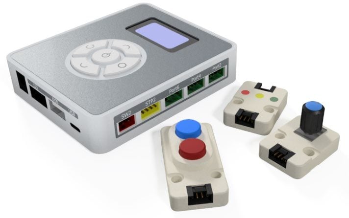
- 1x Magic Box
- 1x USB-A to USB-C Cable
- 1x AC/DC Power Adapter (12 V)
- 3x Common Sensor Cables
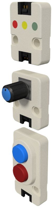
- 1x Dual Button Sensor – PORT 2
- 1x Potentiometer Sensor – PORT 4
- 1x LED Module – PORT 6
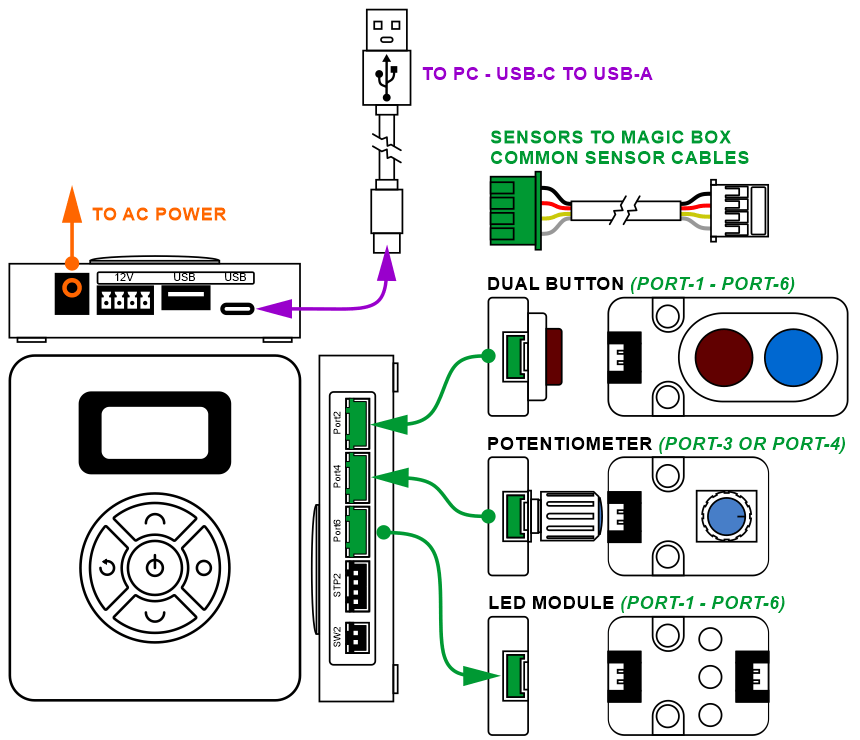
Step 2 – Wire the Magic Box
Wire the Magic Box with sensors as shown.
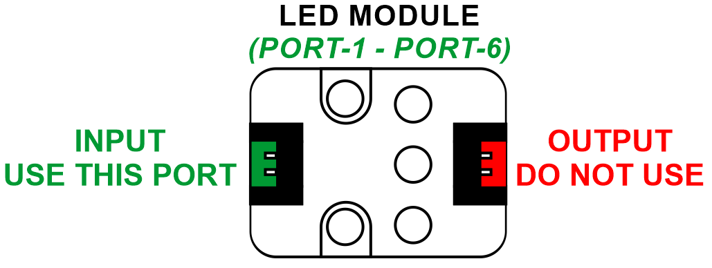
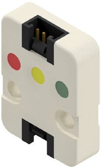
The LED has two ports, one is an input, and one is an output used to connect multiple devices together. Be sure to plug it into the Magic box using the port that is farthest from the LED’s.
![]() Caution: MAKE SURE THE TAB IS PRESSED DOWN ON THE WHITE CONNECTOR WHEN DISCONNECTING ALL SENSORS!!! It is very easy to damage the sensors if the white connector is pulled or tugged on without pressing down the small white tab to release the cable from the sensor housing.
Caution: MAKE SURE THE TAB IS PRESSED DOWN ON THE WHITE CONNECTOR WHEN DISCONNECTING ALL SENSORS!!! It is very easy to damage the sensors if the white connector is pulled or tugged on without pressing down the small white tab to release the cable from the sensor housing.
SECTION 2 – DEFINING INPUTS AND OUTPUTS
INPUTS – Defined as any data or signals that a robot receives that provides feedback about its environment. Information that is brought “into” the controller.
Examples: Sensor Values, Signals from another Device or Robot, User Commands.
OUTPUTS – Defined as an outgoing device or signal that is controlled by the robot. An output is often something that the robot can turn on or off like a light. An output can also be a value that is produced by the robot’s programming.
Examples: LED, Sound, Motor ON/OFF, Motor Speed and Direction Control, Electromagnet, Vacuum Gripper.


SECTION 3 – DEFINING DIGITAL & ANALOG INPUTS
DIGITAL INPUT / SIGNAL – Defined as a signal that can only be read in one of two states: YES or NO, ON or OFF, TRUE or FALSE, HIGH or LOW.
Digital sensors are often wired as either Normally Open (NO), or Normally Closed (NC). When a digital sensor is wired NO, no signal is received until the sensor is triggered. Once the sensor is active, it reports a high or true signal to the controller. Most often this signal is controlled by electric current or voltage (voltage present or not present). Sensors wired NC work in the opposite state.
Examples: Limit Switch, IR Photoelectric Sensor, Inductive Sensor
ANALOG INPUT / SIGNAL – Defined as a type of signal that has a range of values. This value is often affected by the intensity or magnitude of a measured external quantity (something found in the robot’s environment like light or sound).
Examples: Potentiometer, Color Sensor, Humidity Sensor, Light Sensor

SECTION 4 – CONNECTING the MAGIC BOX to DOBOTLAB
Step 3 – Open DobotBlock Lab
Open up DobotBlock Lab in the software.


Caution: NEVER wire anything to the Magic Box while it has power on. ALWAYS turn it off before making connections or damage to the Controller could occur. Be sure to ask your instructor if you have any questions.
Step 4 – Power On & Initial Connections
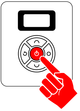
- Once all of the wiring is done (sensors connected), power ON the Magic Box
- Dual Button Sensor – PORT 2
- Potentiometer Sensor – PORT 4
- LED Module – PORT 6
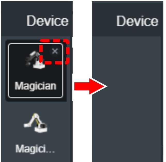
- You do not need a robot for this activity. Delete both the Magician and Magician Lite Devices. Note: This will then default to the Sprite tab once there are no devices loaded.
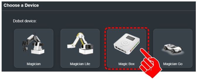
- Click back on the devices tab and click on Choose a Device.
- Select the Magic Box.
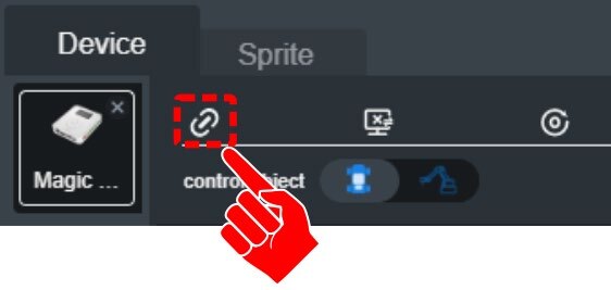
- Connect to the Device.
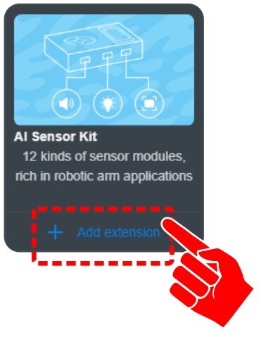
- For this activity, we will need to add an EXTENSION to use the MAGIC BOX. Click the EXTEND icon in the bottom left corner.
- Click on “+ Add extension” for the AI SENSOR KIT.


Teaching Tips:
SECTION 5 – EXPLORATION – DIGITAL INPUTS & with OUTPUTS
SKILL BUILDER 1 – LED MODULE – DIGITAL OUTPUT
Step 5 – LED Basics
- The first device used in this activity is the LED OUTPUT MODULE.
- From the AI SENSOR KIT toolbox, LIGHT CATEGORY, drag over the LED RGB and LED STATE blocks.
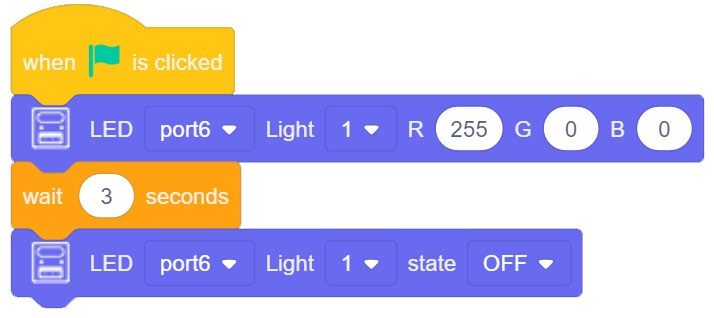
Settings: PORT 6, LIGHT 1
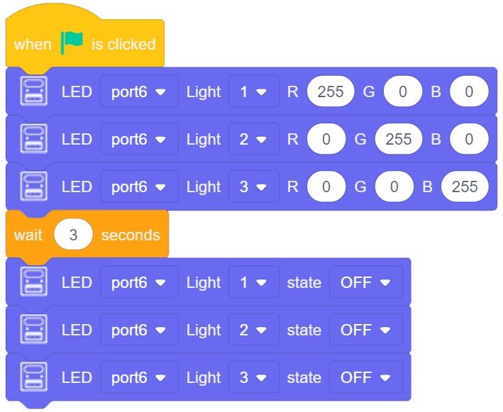
- Now turn on the FIRST LED as RED for 3 seconds, then turn off the LED STATE and end the program.
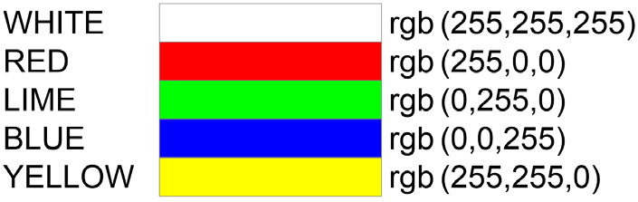
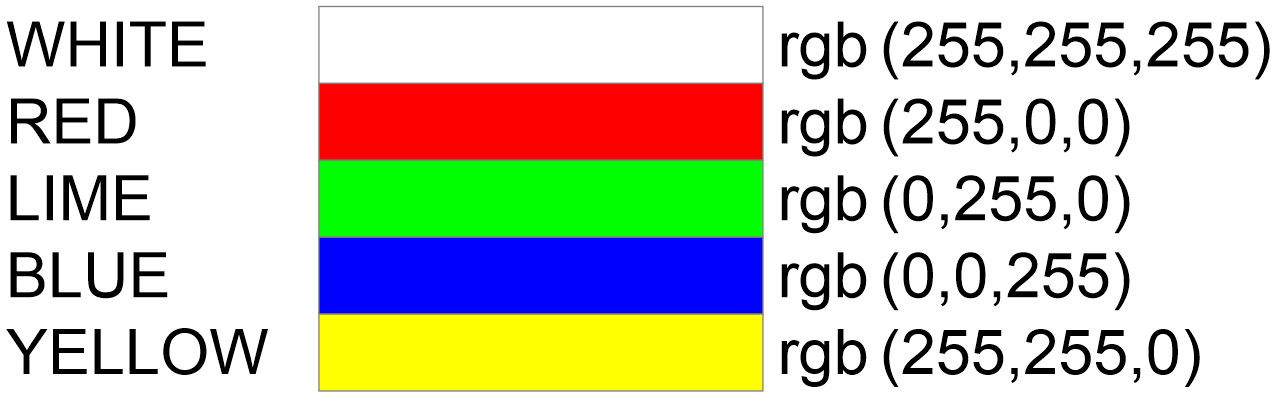
The values to the right are examples of the values used to establish a specific color for the LED Module. The combination of R255 G0 B0 sets the color RED
![]() TEST your code, troubleshoot if necessary.
TEST your code, troubleshoot if necessary.
Be sure the LED module is plugged in correctly and the port is called out correctly.
![]() Can you make the LED display a color like Chartruese? Or Cyan? Look up what those colors are on the internet and see if you can make one of these colors with one of the LED’s!
Can you make the LED display a color like Chartruese? Or Cyan? Look up what those colors are on the internet and see if you can make one of these colors with one of the LED’s!
Step 6 – Multiple LEDs
Next turn on all three LEDS, 1 = RED, 2 = GREEN, 3 = BLUE for 3 seconds
From the AI SENSOR KIT toolbox, LIGHT CATEGORY, drag over the LED RGB and LED STATE blocks.
If the program does not call for the LED Outputs to turn OFF at the end of the program, they will stay on even after the program has ended.
![]() Once the program is completed, run it and see if it works correctly. If it does not work, troubleshoot it until it does.
Once the program is completed, run it and see if it works correctly. If it does not work, troubleshoot it until it does.
Can you make the LED display one after the other for ½ a second each? Can you make the LED’s “chase” one another? How?
If your set up did not work correctly the first time, what did you have to do to make it work?
SKILL BUILDER 2 – DUAL BUTTON – DIGITAL INPUT
Step 7 – Button Variables
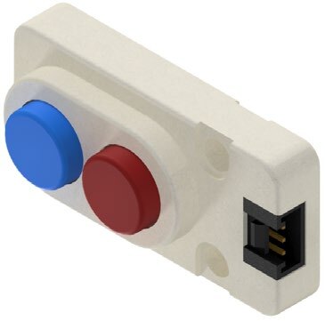
- The second device in this activity is the DIGITAL DUAL BUTTON INPUT MODULE.
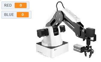
- Since the DUAL BUTTON MODULE is an Input signal, we need to create a way to “SEE” the values that the sensor is reporting to the Magic Box (ON/OFF, 1/0).
- Create TWO new variables (RED and BLUE) and set their initial values to ZERO.
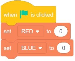
![]() As long as there are check marks next to the variables you created, they should appear in the SPRITE window.
As long as there are check marks next to the variables you created, they should appear in the SPRITE window.

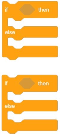
Step 8 – IF / ELSE Logic
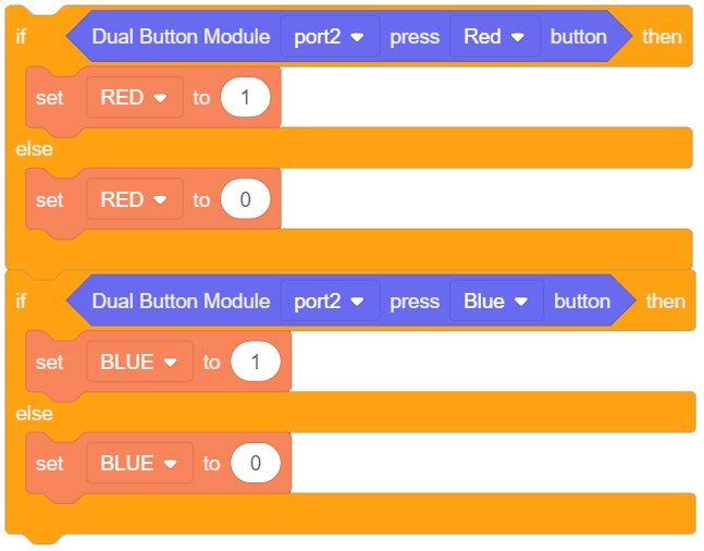
- Setup two separate IF/ELSE Statements.
- CONDITIONS: If the Button is pressed, set the Variable to ONE, else set it to ZERO.
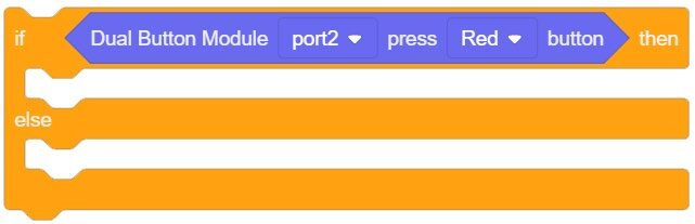
- From the AI SENSOR KIT toolbox, SENSOR CATEGORY, drag over the DUAL BUTTON MODULE blocks and place it inside one of the IF/ELSE Statements.
Settings: PORT 2, RED - This will serve as the condition for this statement. These sensors are wired NORMALLY OPEN (NO).
BUTTON PRESSED = TRUE (ON, 1)
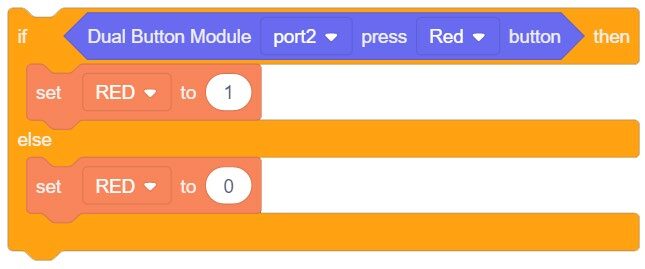
BUTTON NOT PRESSED = FALSE (OFF, 0) - Next, setup what we want the IF STATEMENT to DO. Drag the SET Variable block into both parts of the IF STATEMENT.
STATEMENT IS TRUE = VARIABLE is 1
STATEMENT IS FALSE (ELSE) = VARIABLE is 0 - Repeat this process for the other IF/ELSE statment (or duplicate the first one and change the values).
- You need to continuously evaluate these sensors to see when they are true and false. To do this, we will put them inside a forever loop
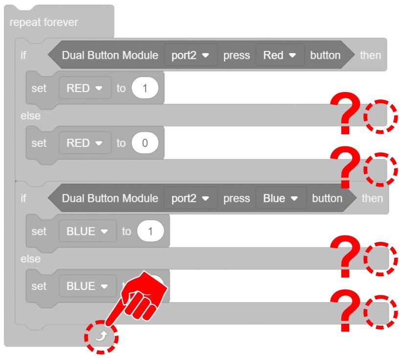
![]() Notice that the IF/ELSE STATEMENTS do not have repeat arrows at the bottom of them. IF STATEMENTS will only be evaluated at the start of each loop. If they are true, they will run the entire process inside the IF portion, FALSE, everything inside the ELSE portion. IF STATEMENTS then move onto the next section of code (NO REPEAT). Both of our Statements do not have a perceivable time needed to run the code and move on, this will allow both buttons to be pressed at the same time and both return true conditions.
Notice that the IF/ELSE STATEMENTS do not have repeat arrows at the bottom of them. IF STATEMENTS will only be evaluated at the start of each loop. If they are true, they will run the entire process inside the IF portion, FALSE, everything inside the ELSE portion. IF STATEMENTS then move onto the next section of code (NO REPEAT). Both of our Statements do not have a perceivable time needed to run the code and move on, this will allow both buttons to be pressed at the same time and both return true conditions.
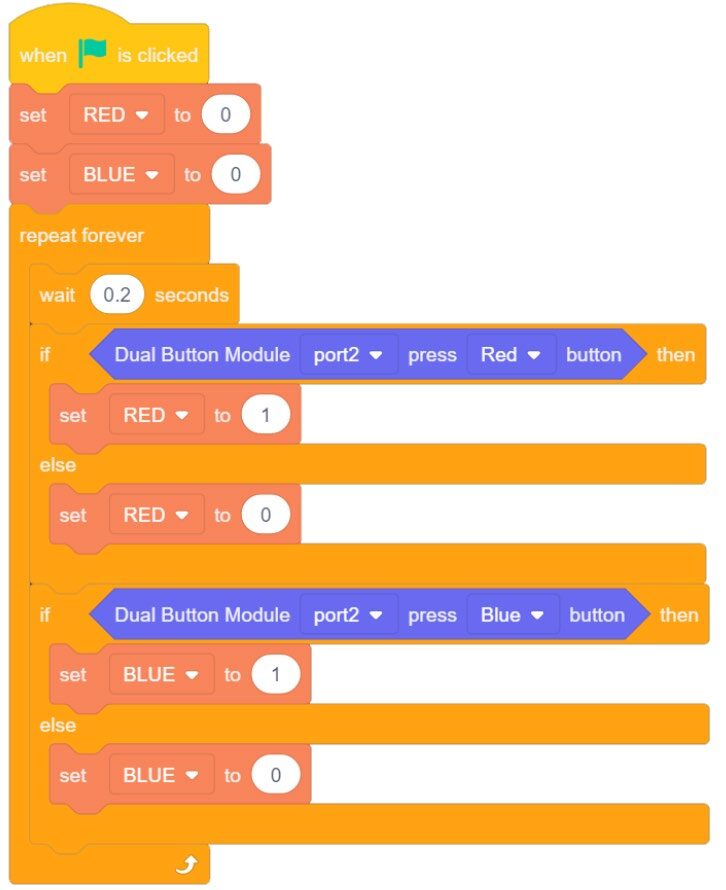
Add a Micro Wait inside the Forever Loop.
Once the program is completed, run it and see if it works correctly. If it does not work, troubleshoot it until it does.
If your set up did not work correctly the first time, what did you have to do to make it work?
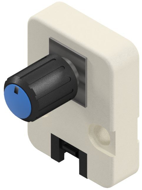
SKILL BUILDER 3 – POTENTIOMETER KNOB – ANALOG INPUT
Step 10 – Potentiometer Reading
- The Third device used in this activity is the POTENTIOMETER KNOB INPUT MODULE. This device is an analog input.
- Since the POTENTIOMETER MODULE is an Input signal, create a VARIABLE as a way to “SEE” the values the sensor is reporting to the Magic Box.
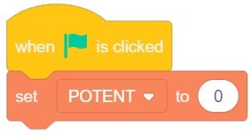
- Create a new variable (POTENT) and set its initial value to ZERO. This will clear out any initial values for this variable.
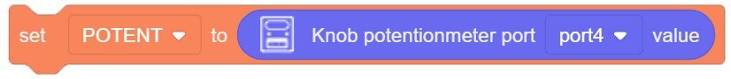
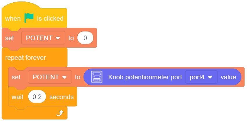
- Next inside a FOREVER LOOP block, assign the variable’s value to the sensor’s value.
- From the AI SENSOR KIT toolbox, SENSOR CATEGORY, drag over the KNOB POTENT VALUE block.
Settings: PORT 4 - Drag the sensor’s value into the SET VARIABLE block.
- Place a SMALL MICRO WAIT (0.2) after setting the variable to the sensor’s value before it repeats the loop.

![]() Once the program is completed, run it and see if it works correctly. If it does not work, troubleshoot it until it does.
Once the program is completed, run it and see if it works correctly. If it does not work, troubleshoot it until it does.
If your set up did not work correctly the first time, what did you have to do to make it work?
- What was the Highest Value the sensor reported?
- What was the Lowest Value the sensor reported?
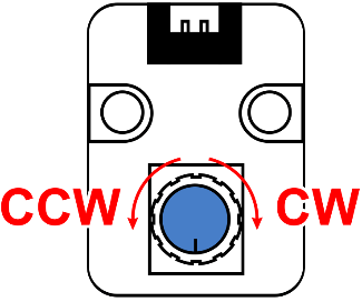
- Which direction increases the value (CW / CCW)
CHALLENGE
SECTION 6 – CONTROL OUTPUTS WITH INPUTS
Challenge Scenario: ALL of the conditions below are in the same program
- When the BLUE button is pressed, LIGHT 1 will turn BLUE
- When the RED button is pressed, LIGHT 3 will turn RED
- The corresponding lights will be OFF when the corresponding buttons are NOT pressed
- Divide the POTENTIOMETER High value into thirds –
- **NOTE – Use GREATER THAN, LESS THAN, and possibly the AND OPERATORS for the next portion to create the needed conditions (Hexagon Shapes) for the analog sensor?
- When the POTENTIOMETER value is in the bottom third or the top third, LIGHT 2 will be WHITE
- When the POTENTIOMETER value is in the middle third, LIGHT 2 will be YELLOW
Once the program is completed, run it and see if it works correctly. If it does not work, troubleshoot it until it does. SHOW YOUR INSTRUCTOR WHEN THE CHALLENGE IS COMPLETE
If your set up did not work correctly the first time, what did you have to do to make it work?
Teaching Tips:
CONCLUSION
- What type of values are reported from analog sensors?
- What type of sensors would be would you find in an automated vehicle? List as many as you can think and identify them as analog or digital.
- What type of sensors might a robot use/need to allow people to work near the robot or inside its work envelope?
- What are the RGB values for
MAGENTA: ORANGE: GREY:
GOING BEYOND
Finished early? Try some of the actions below. When finished, show your instructor and have them initial on the line.
- RED BUTTON is pressed, LIGHT TURNS RED, but only for 3 seconds (even if the button is still held) _________
- ALL three lights are off unless, the red button and the blue button are pressed and held as well as the potentiometer is at its lowest setting.
If all three conditions are met, make all three lights turn magenta… until the three conditions are not met again. _________ - When the RED BUTTON IS PRESSED make the 3 LED’s “chase” one another to the right as RED. When the BLUE BUTTON IS PRESSED, make the LED’s “chase” one another to the left 5 times as BLUE. _________
- When the POTENTIOMETER is in the FIRST THIRD OF ITS TRAVEL Turn on the LED TO RED. When the POTENTIOMETER is in the MIDDLE THIRD OF ITS TRAVEL Turn on the LED TO YELLOW. When the POTENTIOMETER is in the LAST THIRD OF ITS TRAVEL Turn on the LED TO GREEN. _________