Lesson Modules
Teaching Tips:
PROCEDURE
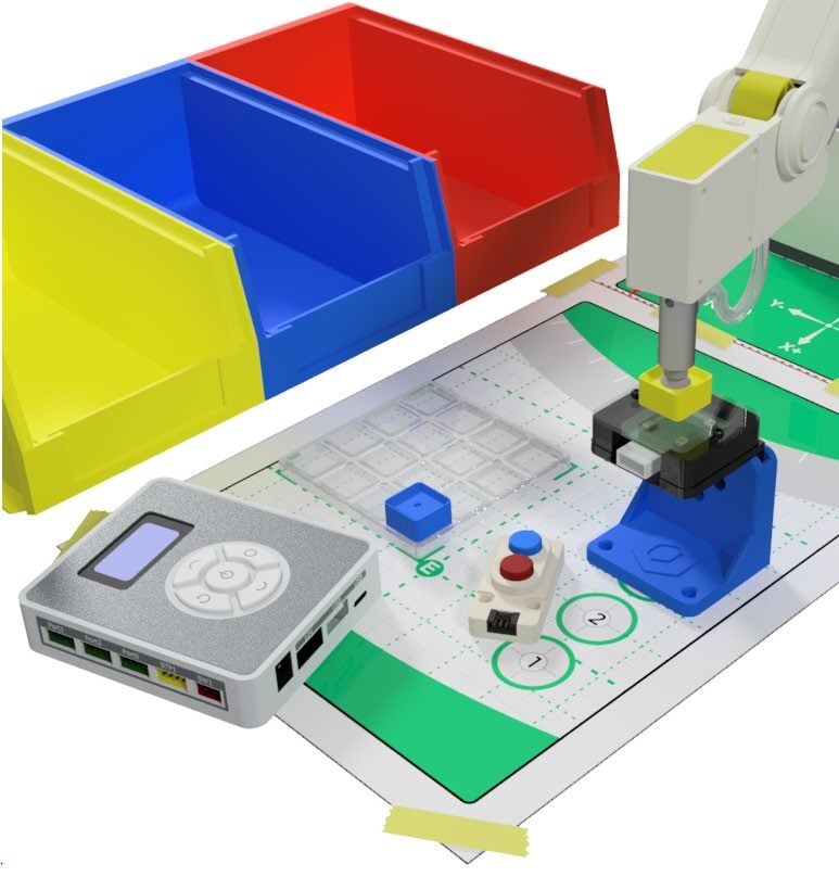
SECTION 1 – WIRING the MAGIC BOX AND SENSORS
Caution: NEVER wire anything to the Magic Box while it has power on. ALWAYS turn it off before making connections or damage to the Controller could occur. Be sure to ask your instructor if you have any questions.
- For this activity, you will need:
• 1x Magic Box
• 1x USB-A to USB-C Cable
• 1x AC/DC Power Adapter (12V)
• 2x Common Sensor Cables
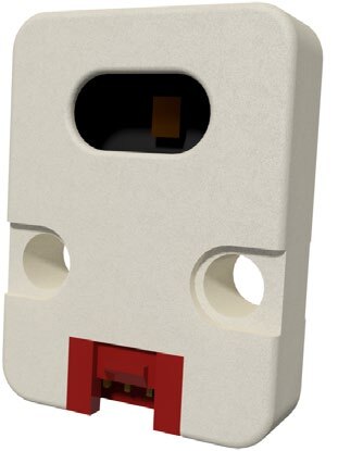
• 1x Color Sensor – PORT 4
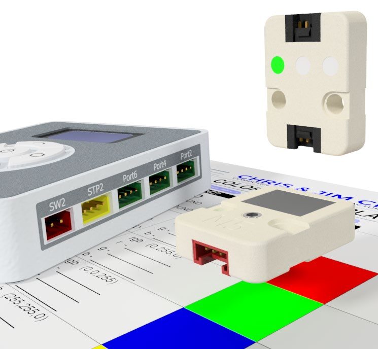
• 1x LED Module – PORT 6 - Wire the Magic Box as shown to the right
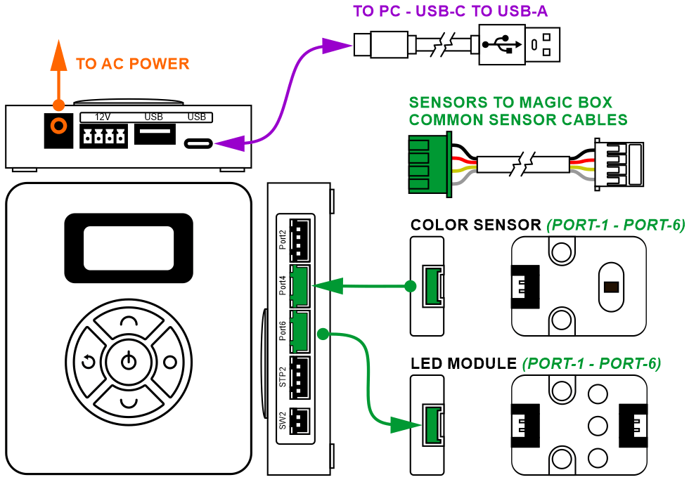
Caution: MAKE SURE THE TAB IS PRESSED DOWN ON THE WHITE CONNECTOR WHEN DISCONNECTING ALL SENSORS!!! It is very easy to damage the sensors if the white connector is pulled or tugged on without pressing down the small white tab to release the cable from the sensor housing.
SECTION 2 – CONNECTING the MAGIC BOX to DOBOTLAB
- Open up DobotBlock Lab in the software.


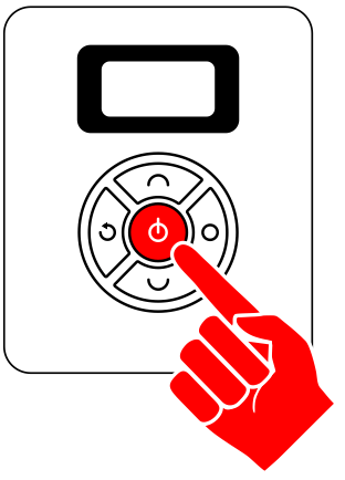
- Once all of the wiring is done (sensors connected), power ON the Magic Box
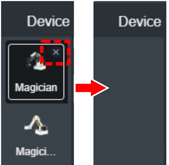
- No robot is necessary for this activity. Delete both the Magician and Magician Lite Devices.
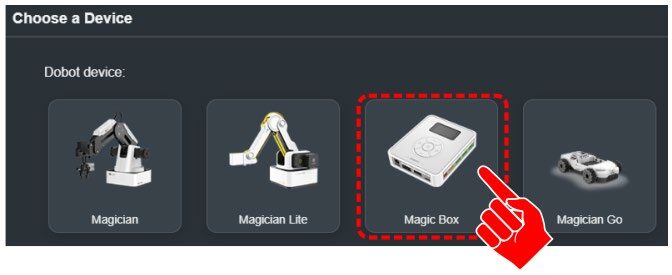
Note: This will send you over to the Sprite tab once there are no devices loaded. - Click back on the devices tab and click on Choose a Device

- Select the Magic Box
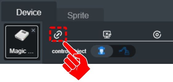
- Connect to the Device

- For this activity, you will need to add an EXTENSION to use the MAGIC BOX. Click the EXTEND icon in the bottom left corner.
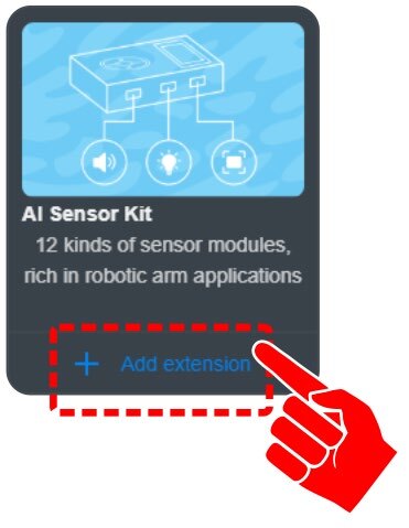
Click on “+ Add extension” for the AI SENSOR KIT.

SECTION 3 – EXPLORE COLOR SENSOR
The color sensor can produce two different sets of values.
1. The sensor can identify the color of the object and return a set of RGB values
2. The sensor can identify six preset colors and return a true value if one of these colors are detected.
BLACK, WHITE, RED, GREEN, BLUE, YELLOW
ANY GREEN
PORT
PORT 1-6
SKILL BUILDER 1 – FIND INDIVIDUAL VALUES FOR RED / GREEN / BLUE
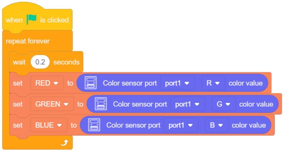
- Drag over a Color Sensor Color Value block from the AI SENSOR KIT toolbox
This block will report a separate numeric value for the amount of R, G, B the sensor sees. - Change the PORT value to the port you are using
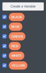
- Next, create three separate VARIABLES RED / GREEN / BLUE
- Create the program to the right.
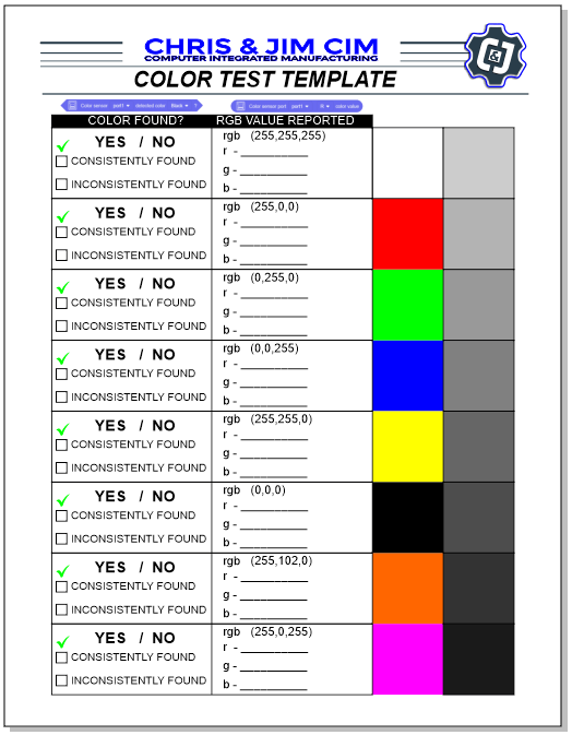
The 0.2 MICROWAIT will slow down the program. It only allows a new sensor values to be pulled (looked at) every 0.2 seconds - Print a copy of the Color Test Template
- Run the program and document the values reported to the variables by the sensor.

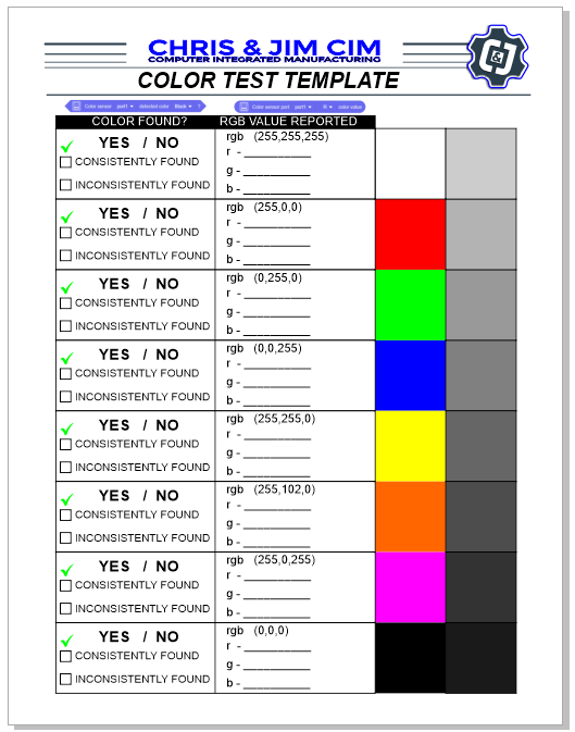
Are the values reported to the variables the same or close to the typical values used in industry for each color?
Is there a pattern to the numbers reported that can be used to alter the variables (a computation / formula) to show a value that better represents the values expected? If so, what formula computation could be used for the variables?
Using the grey scale colors, what type of values are reported when no red, green, or blue values are present?
SKILL BUILDER 2 – DETECT KNOWN COLORS
- Drag over a Color Sensor Detected Color block from the AI SENSOR KIT toolbox
- Change the PORT value to the port you are using
This command will report if a specific color is present.
BLACK, WHITE, RED, GREEN, BLUE, YELLOW
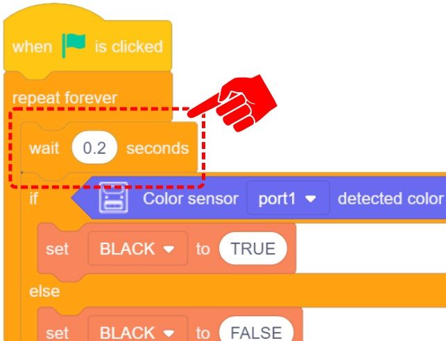
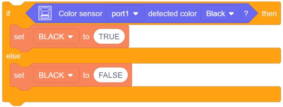
One way to use this block is to create sets of IF/ELSE statements. If the color is TRUE/PRESENT set the variable to 1, else set it to 0

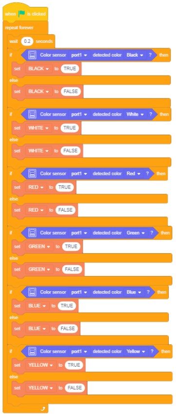
- Using the same program from TEST 1, create additional variables for the remaining colors (six total).
- Create an IF/ELSE statement for EACH color
- Link all of the IF/ELSE statements together inside a FOREVER Block
- Insert a small 0.2 second MICROWAIT at the begging of the program to slow the cycle down
- Run the program and document if the colors are seen correctly (circle YES or NO).
![]() Ensure the PORT number matches the port you are using and that the color is different for each Statement.
Ensure the PORT number matches the port you are using and that the color is different for each Statement.
In previous activities, the SET VARAIBLES have been set to INTERGERS (whole numbers) to represent YES (1) and NO (0). Notice in the example to the right, STRING values (text) can also be used.
Check the “Consistently Box” if the correct color is reported by the sensor (all the time or almost all the time)
or
Check the “Inconsistently Box” (sometimes) if the value reported by the sensor is often incorrect or sometimes does not read and report the color at all.
Teaching Tips:
CHALLENGE
SECTION 4 – USE the COLOR SENSOR TO CONTROL THE LED
- Use the values reported by the color sensor to control the color of LED1
As the color sensor is held over the Color Test Template, the color of the LED 1 will change color to match the color seen (sensor reports RED, LED becomes RED). - As an added level of intelligence to your program, have the variables show the value received as well.
- The LED will show no color when black is received.
- Do not use the grey scale for this activity.
- Do not use ORANGE and MAGENTA for this activity.
Continue to test your program until it works as needed.
If your set up did not work correctly the first time, what did you have to do to make it work?
CONCLUSION
- How accurate was the color sensor at displaying RGB values?
- How accurate was the color sensor at determining colors from the color test template?
- Would you be able to determine the color of the cubes provided by your instructor using this color sensor? Defend your answer, and then try it.
- Explain how you might be able to use the robot with the color sensor. What tasks will you be able to do with it?
GOING BEYOND
Finished early? Try some of the actions below. When finished, show your instructor and have them initial on the line.
- _________ 1. Get some colored cubes from your instructor. Write a program to determine the color of the blocks (hint: this is already done) Test it. How accurate is it at determining block color?
- _________ 2. Program the LED to mimic the color of at least 4 different color blocks. Example: (Red Block? Red LED turns on, ect.)