Lesson Modules
Teaching Tips:
PROCEDURE
SECTION 1 – CONNECTING the CAMERA to the MAGICIAN
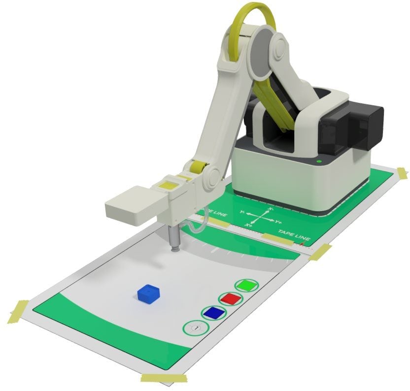
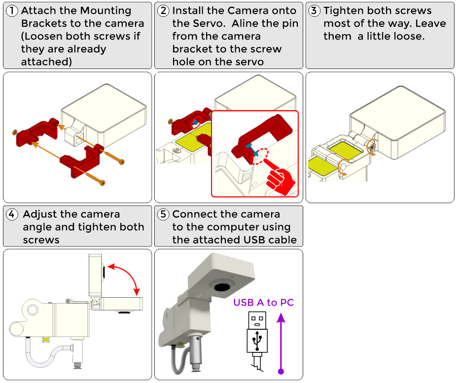
1. Install the camera on the Magician Lite (Any USB camera can be used, be creative in mounting it.)
SECTION 2 – CREATING THE CLASSIFICATIONS and TRAINING the MODELS
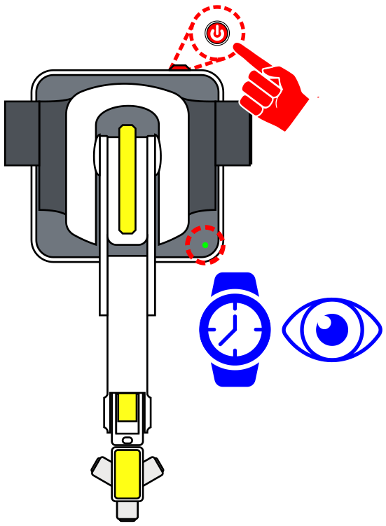
Once the USB camera is mounted to the robot and the USB cable is plugged into the computer, power ON Robot. WATCH and WAIT for the robot to completely power on (GREEN INDICATOR)

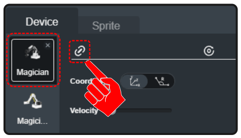
1. Open up DobotBlock Lab in the software and connect to the robot.

2. Follow the same process from previous activities to add the Magician as a device and connect the software to it (establish communication).
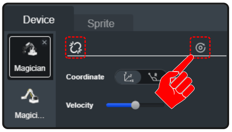
3. Once the robot is connected, we need to home the robot to set its home position.
Before HOMING the robot, make sure the robot’s WORK ENVELOPE, the area in which the robot can reach, is clear.
Select the HOME icon to start the robots homing process. HOMING the robot will return and set the robot to its initial HOME position.
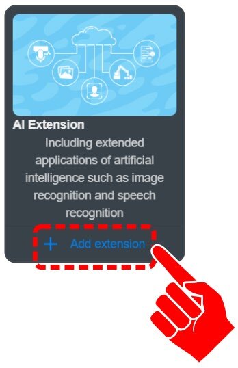
4. Click on “+ Add extension” for the AI EXTENSION.
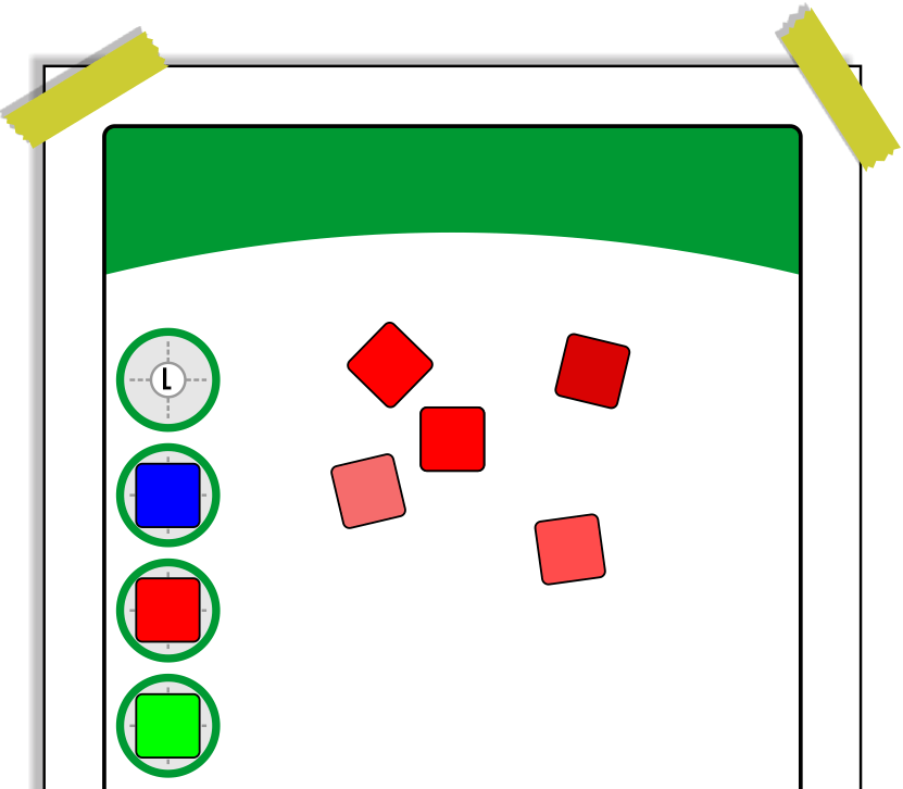
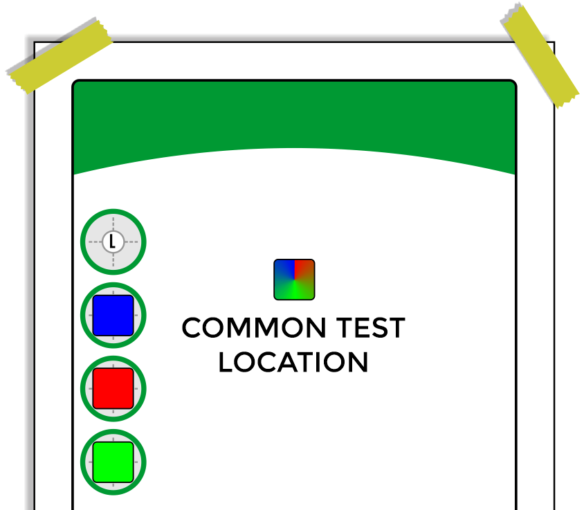
5. Tape a Field Diagram down to the table.
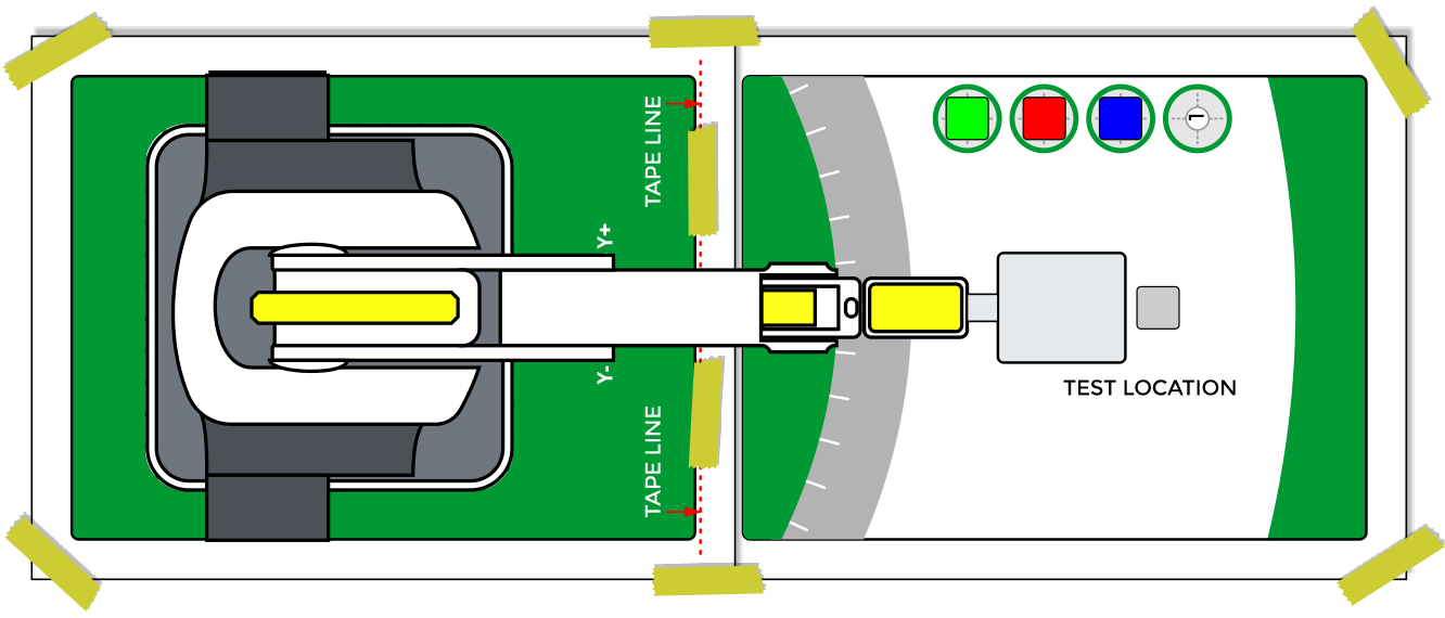
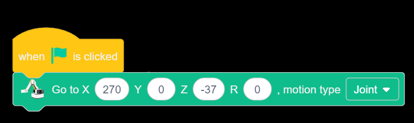
6. Send the Robot to a known position to use the camera.
For this activity use coordinates similar to:
X270 Y0 Z-37 R0.
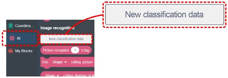
7. Click on NEW CLASSIFICATION DATA from the AI category in the block toolbox.
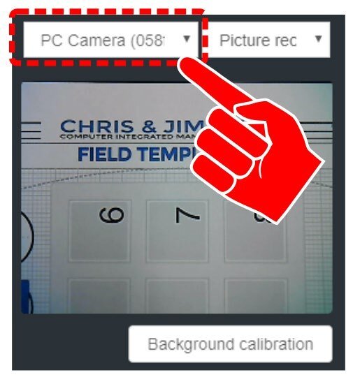
8. Click the drop down for the camera device selection. Choose the Camera attached to the arm.
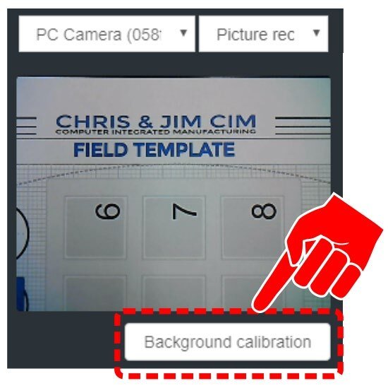
9. The background used in this activity is not a plain white field. Choose Background calibration. This will allow the software to ignore the background as it learns the images during training.
![]() When the background of the camera is not pure white, click this button to calibrate the background to improve the automatic recognition rate. Note: pure white background is always the best choice. Before calibration, please make sure that there is no debris in the camera’s field of view. Do not place the objects to be trained in the field until after calibration.
When the background of the camera is not pure white, click this button to calibrate the background to improve the automatic recognition rate. Note: pure white background is always the best choice. Before calibration, please make sure that there is no debris in the camera’s field of view. Do not place the objects to be trained in the field until after calibration.
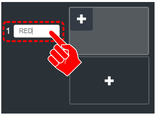
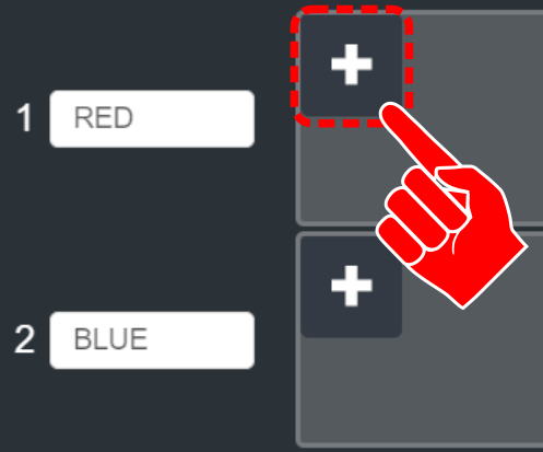
10. Label the first classification as RED.
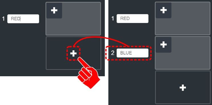
11. Click the Plus in the CENTER of the next window to create a second classification. Label the second class as BLUE.
The software now needs to be taught how to distinguish the difference between the two classifications.
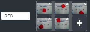
12. Place the red cube within the camera’s field of view. Click the PLUS in the top left of the RED class window. A picture will be taken and stored. Move the block to a new location in the field and click the plus again. This will create a second image for the software to use for comparison. Take at least three different images. Try to vary angle, location, different faces, different lighting, and different shadows (any condition that could be present during evaluation).
13. Repeat the process for the BLUE class.
14. Now that the robot has resources to compare against, click the TRAINING MODEL to move to the next phase (testing).
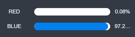
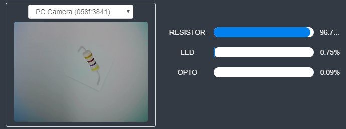
15. Place RED or BLUE cube in the camera’s vision. The goal is to have model matching that is close to 100%. Click FINISH to complete the model training.
![]() There can be a delay in switching between classes. If the model matching fails or is not near 100% for each class, click <Return, recollect images, change the lighting, or add additional pictures to re-train the classification.
There can be a delay in switching between classes. If the model matching fails or is not near 100% for each class, click <Return, recollect images, change the lighting, or add additional pictures to re-train the classification.


Teaching Tips:
SECTION 2 – TESTING the MODELS with BLOCK CODE
SKILL BUILDER 1 – COMPARING NEW IMAGE TO STORED DATA (MODELS)
Now that the classes have been created and the models have been trained, create a block program to test the accuracy of the setup.
1. Create two variables (RED & BLUE)
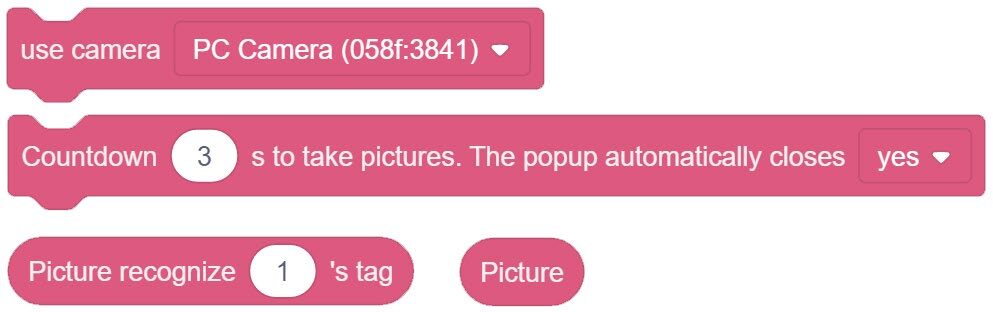
2. This program will use a few new blocks from the AI Extension category.
A. Camera Category – USE CAMERA
B. Image Acquisition – COUNTDOWN to TAKE PICTURE
C. Image Acquisition – PICTURE
D. Image Recognition – PICTURE RECOGNIZE
3. The program will also require one new block from the OPERATORS category
4. Link the blocks together as seen to the right.
This series of blocks will create a condition that decides if the picture it takes fits into the stored model data for the RED classification.
![]() Do not use a variable, be sure to just type “RED” or “BLUE”.
Do not use a variable, be sure to just type “RED” or “BLUE”.


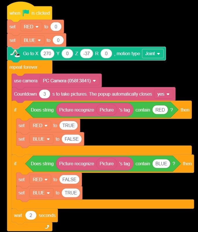
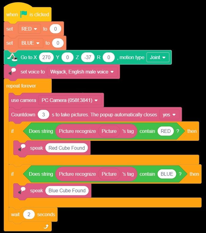
5. Using the conditions created, the variables, and a few if statements, create the program to the right that will test the models saved.
A. Initialize the Variables as False.
B. Send the robot to or near its HOME location.
C. Choose which camera to use.
D. Pause for three seconds and take a picture (the camera popup window will automatically pop up and take the picture. The new picture is stored as “PICTURE).
E. IF Statement – Ask the question if the new “PICTURE” recognizes/matches the ones stored in the RED class or BLUE class. When they match, set the matching variable to TRUE and display that value for 2 seconds before looping and retesting the model.
Run the program and test the stored models for the RED and BLUE cube.
What if there were no block present? Could you make a new classification called “none” and teach it what no block looks like? Try it!
If your set up did not work correctly the first time, what did you have to do to make it work?
SKILL BUILDER 2 – ADDING AUDIO FEEDBACK
Providing user feedback can be a valuable part of programming. Up to this point, the programs have used variables and or LEDs to display visual feedback. This skill builder will show how to add AUDIO FEEDBACK to the program. To do this, the program will need a few blocks from the AI Extension category.
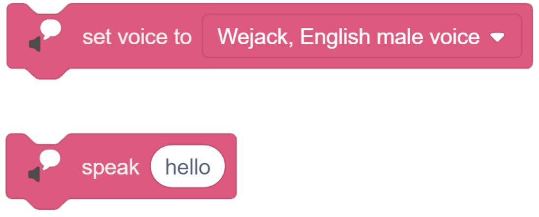
1. Drag over the SET VOICE TO and the SPEAK blocks from the Text to Speech section of the AI Extension category.
2. In order to keep the program small, remove the variables.
3. Add the Set voice to the header of the program.
4. Replace the variables with the SPEAK Block.
Run the program and test the stored models for the RED and BLUE cube with audio feedback.
If your set up did not work correctly the first time, what did you have to do to make it work?
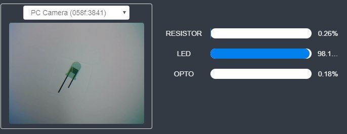
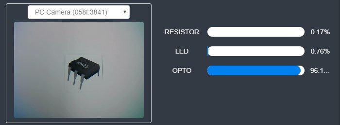
SKILL BUILDER 3 – IMAGE RECOGNITION with NON-CUBE OBJECTS
It may appear that this program is only comparing the color of the cubes. In reality, the images are also comparing things such as size, shape, form, objects with multiple colors and details. They are full color photos that the program is using to build a 3D picture of what it is looking for. This skill builder will test this capability.
1. For this portion of the activity, lower the Camera’s Z to take larger sampling image of the objects & replace the template with a piece of white paper.
Use coordinates similar to:
X270 Y0 Z-65 R0.
2. Save the current file and start a new one. Create a NEW CLASSIFICATION DATA model.
3. Create THREE classifications
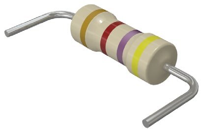
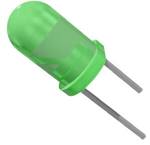
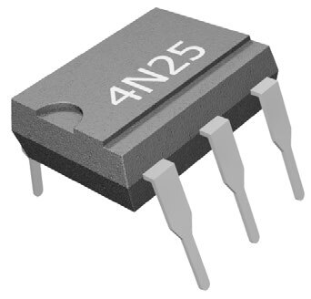
A. Resistor B. LED C. Isolator
4. Repeat the process used for the cubes with the electrical components from the handshaking activities. Again, use different angles, orientations, and locations (the more photos taken, the more data the software has to use for comparison).
![]() If you did not do any of the handshake activities, see if your instructor can give you a few electronics components to test.
If you did not do any of the handshake activities, see if your instructor can give you a few electronics components to test.
5. Use either Variables (visual feedback) or Speech (audio feedback) to test the program’s image recognition capabilities.


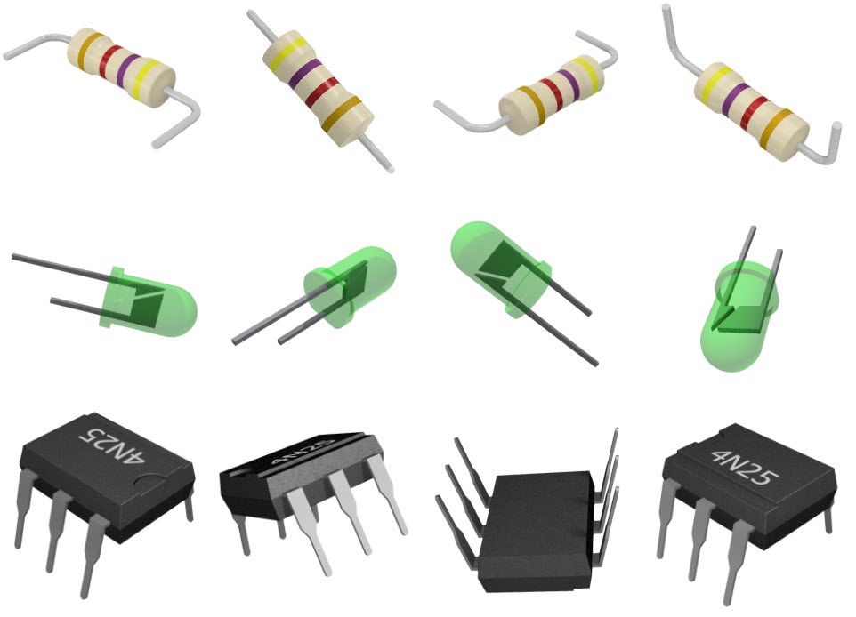
![]() Print and cut out the images to the right and use them as the reference images (remove the blue border). The images can be used more than once if additional data is needed, just rotate or move the images.
Print and cut out the images to the right and use them as the reference images (remove the blue border). The images can be used more than once if additional data is needed, just rotate or move the images.
Continue reteaching the models as needed to get consistent results in the 90% or better range.
Run the program and test the stored models for the electrical components.
If your set up did not work correctly the first time, what did you have to do to make it work?
CHALLENGE
SECTION 3 – USE the CAMERA to SORT 3 DIFFERENT COLOR CUBES
Develop a program that will test four different cube colors using the camera.
- Start at a HOME location.
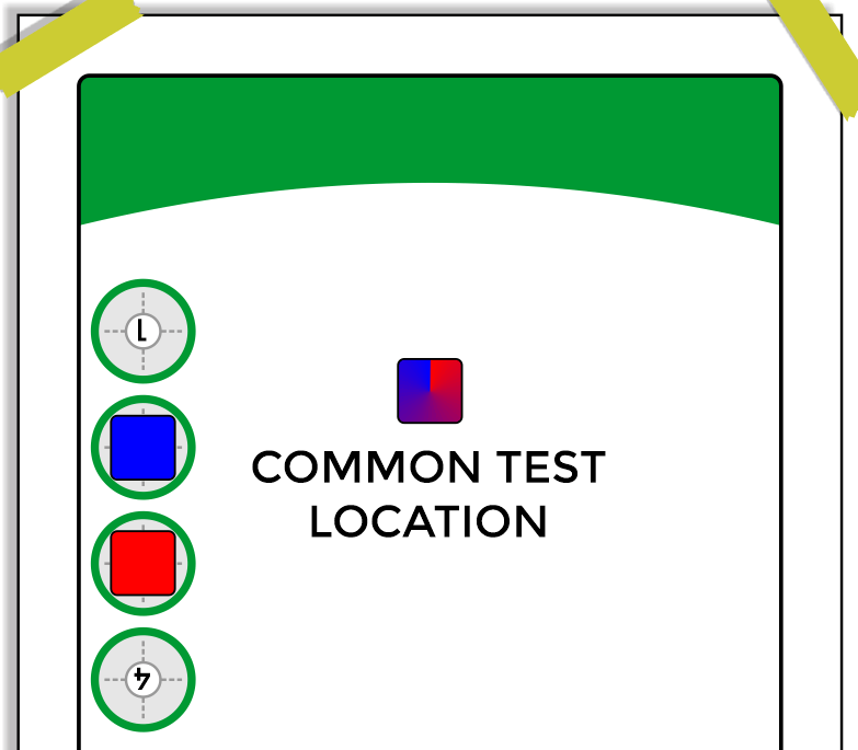
- Send the robot to a common test location.
- Test the color of the cube with the camera.
- Move to a pick-up location.
- Pick up the cube and place it in a designated drop off location.
- Loop the program for another cube.
Teaching Tips:
CONCLUSION
- Is the camera sensing color or shape only? One or the other? How do you know?
- If you printed the electrical components in black and white, would it still work?
- What percentage was the accuracy for your robot in identifying objects? If it was lower than 100%, what could you do to increase its accuracy?
GOING BEYOND
Finished early? Try some of the actions below. When finished, show your instructor, and have them initial on the line.
- _________ 1. Complete the skill builder above and have your instructor check your work.
- _________ 2. Complete the Challenge above and have your instructor check your work.
- _________ 3. What happens when there is nothing in the camera’s field of view? Can you make the robot tell you that there is nothing there? How?
- _________ 4. Get three or four different electronic components from your instructor. The actual objects, not photographs. Teach the classifications and see if the robot can identify the actual objects.
- _________ 5. If you have the sensor kit, teach it three different sensors. (like the Potentiometer, the light sensor, and the PIR sensor) Can it accurately see the difference?