
Lesson Modules
Teaching Tips:
This first module gives an introduction to the sensors of the NAO robot.
You can let the students look at the NAO and try to identify the sensors he has.
Senses of the NAO
Humans have five senses - hearing, sight, touch, smell and taste. In addition, there are other lesser known human senses. They include the sense of balance, the sense of temperature, and kinesthetic sense. Kinesthetic sense is the ability to know where different parts of your body are without relying on other senses. It is this kinesthetic sense that enables you to close your eyes and touch parts of your body.
There are robots that are capable of performing similar functions to all the senses listed above. The physical devices in robots that sense the environment are called sensors.
Teaching Tips:
You can find the file to download for this module here.
The step by step guide to the programming is under CLASS VIEW
The students can take turn to run their code on the real robot. Or you can just demo the code yourself and in later modules, they will have the opportunity to run their code.
Some background about LEDS can be found here :
Besides its motors, the NAO has other forms of output. It has speakers on both sides of its head that it can use to play sounds and speak - we have used the text-to-speech capabilities in earlier modules. The NAO also has a variety of light-emitting diodes (LEDs) that can change brightness and color. As you may have learned from physics, diodes allow current to flow in only one direction. LEDs are a class of diodes that emit light when current flows through. The figure below shows the electronic symbol of an LED.

Around each of the NAO’s speakers are 10 LEDs. These LEDs are blue in color and form a ring around the speaker. You may have noticed these LEDs switch on as the NAO is booting up. Besides turning these LEDs on and off, you can also vary their brightness. There are also 3 similar LEDs on the top of the NAO’s head that are blue in color.
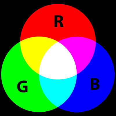
In each of the NAO’s “eyes” there are 8 color LEDs. Color LEDs can show any color, by combining different intensities of three primary color LEDs - red, green and blue. For example, when yellow is displayed, the red and green are on and blue is off. You may have seen the figure below, which shows how the primary colors combine to form any color.
The NAO has a color LED in its chest, and one on each foot. Similar to the eye LEDs, we can choose what color the LED should display by changing the intensity of red, green and blue.
Basic Task: Light Up
The NAO has foot bumpers which can be pressed, and various LEDs that light up. In this lesson, we will make the NAO’s eye LEDs change color when a foot bumper is pressed.
1. Open Choregraphe and create a program that makes the LED light differently if the left bumper or the right bumper is pressed.
2. You won't be able to see it on the simulated robot but the code should work.
Teaching Tips:
This module explains a basic concept in computer science, the Finite State Machine or FSM.
You can let the student read the definition of it and show them the diagram in the CLASS VIEW as a support to understand.
Tips: You can ask students to draw their own diagram before showing them the answer under CLASS VIEW
Finite State Machines
A finite state machine, or FSM, is an abstraction commonly used in computer science and robotics. A finite state machine includes states (a finite number of them) and transitions. We will use a running example to explain these concepts.
Suppose that an exam is coming up, and you are at home preparing for it over the weekend. Your behaviors (what you do during the weekend) can be described with a finite state machine. Your state can be described using two features: how prepared you are for the exam (prepared or unprepared), and how much energy you have (rested or tired). The goal is to ultimately be both prepared and rested at the end of the weekend.
An FSM state must completely describe the situation without any external information. So, one state would be (prepared and rested). Notice that we combined both features into a single state. There will be four states in total - (prepared and rested), (prepared and tired), (unprepared and rested) and (unprepared and tired). Each of the four states contains all the information about the situation. Within a FSM, only one state is active at a time.
So in our example, say that we start off in the (unprepared and tired) state, since a week of classes just ended (so we’re tired), and we haven’t had time to study for the exam yet. We want to end up in (prepared and rested). To go from state to state, we have to define the transitions. Transitions move us from one state to another, and can be triggered through actions or events. Intuitively, actions are things that are performed by choice, and events are things that occur. We will use actions in the example below, and discuss events at the end of this section.
Some actions we can take in our example are studying, playing, and sleeping. If we’re tired, then sleeping should make us rested. Thus, the transitions from (prepared and tired) to (prepared and rested), and from (unprepared and tired) to (unprepared and rested), are triggered by sleeping. Similarly, the action studying will make us prepared for the exam but will tire us out. However, we can only perform this action if we are rested. As such, there is a transition from (unprepared and rested) to (prepared and tired) that is triggered by studying. The last action is playing, which can be performed at any state. However, playing causes us to both become tired and forget what we’ve learned. So, there are transitions from all the other states to (unprepared and tired) that are triggered by playing.
A FSM can be illustrated with a diagram.Circles indicate states, and arrows indicate transitions. The initial state is illustrated by a straight arrow that points to the state that we start out in.
Besides triggering transitions with actions, events can also be used. Events are things that happen, that are typically caused by something external to the FSM. For example, an event could be the teacher reducing the scope of the exam. This event might transition us from (unprepared and tired) to (prepared and tired), since we already know the areas covered in the revised exam even without studying.
Teaching Tips:
You can find the code for this module here
The step by step guide to the program is under CLASS VIEW and can be shown to the students.
Intermediate Task: Switching States
In this task, we will make the robot turn its ear LEDs on and off by pressing one foot bumper, and toggle its eye colors by pressing the other foot bumper. We will implement this using a finite state machine.
Similar to our finite state machine example in the section above, we have two features in the states. The features are: whether the ear LEDs are on (on and off), and what color the eye LEDs are set to (A or B). Thus, we have four states.
Each press of a foot bumper is an event that will trigger a transition to a different state.
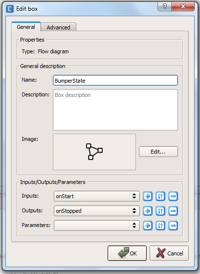
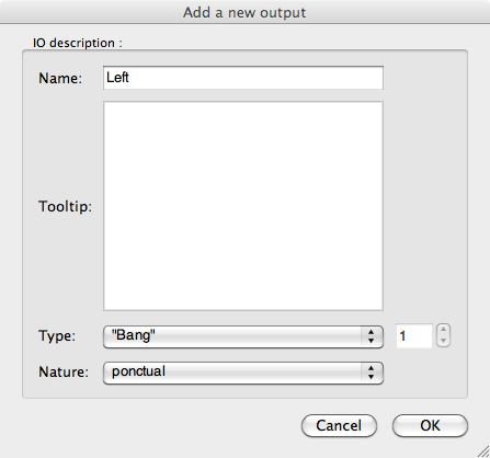
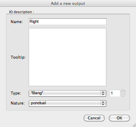
1. First, we’ll create one of the states. Add a diagram box named “Ears on and eyes A”, and add two outputs, “Left”, and “Right” to the box
2. Double-click on the custom box, and a new flow diagram will show up. Add a Bumpers box, an Eyes LED box, and a Ears LED box, and connect them.
3. Set the ears intensity to 100%, and set both the eye colors to a color of your choosing, which we will refer to as color A. The state (ears on and eyes as color A) is now defined with these three boxes. The two outputs, left and right, correspond to the events of the left foot bumper and right foot bumper being pressed.
4. Click on root to go back to the main flow diagram, then copy and paste these three boxes to create four states, as shown below. Rename each box to correspond to the state it represents.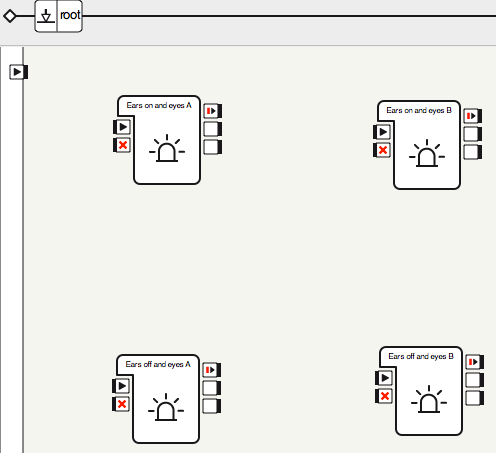
5. Double-click each of the three new states, and edit the Ears LEDs and Eyes LEDs boxes so that they match the state they are in.
6. You have created the four states. The states the boxes represent, clockwise from the top-left are: (ears on and eyes as color A), (ears on and eyes as color B), (ears off and eyes as color B) and (ears off and eyes as color A).
7. Now add the transitions between them.
8. Run the behavior. Press the bumpers to ensure that all the states work as intended. Congratulations! You have implemented a finite state machine.
Teaching Tips:
The activity in this module is optional. It is meant to stand alone and give students an understanding of different sensors of the NAO robot and how to plot them on a graph.
Intermediate Task: Reading Raw Data From the Sensors
In this lab, we will learn how to observe the raw sensor values from the robot from within Choregraphe as well as within the Monitor Desktop progam.
1. Within Choregraphe on the pull-down menu click on the View > Memory Watcher option. A window, or extra tab should appear in the bottom center of the main window with the title “Memory Watcher”. This is where we can observe some of the sensors and inputs that are stored in the NAO’s memory.
2. Click on the memory watcher tab. The window should be blank with a short string that reads “<select memory keys to watch?”. Double click on this value, and a dialog window will pop up.
3. When the dialog window pops up. Check “View Devices” at the bottom, and scroll down until you find “Device/SubDeviceList/InertialSensor/AccX/Sensor/Value”, and check this item. Also select “.../AccY/Sensor/Value” and “.../AccZ/Sensor/Value”. These are the accelerometer (A sensor that detects acceleration and tilt) (see sensor section) readings along the x, y and z axes. You will have to expand upon the sub-folders until you get the proper selections, so go into devices, subDeviceList, InertialSensor, etc… to check the boxes as shown below. When you are done, Click OK. 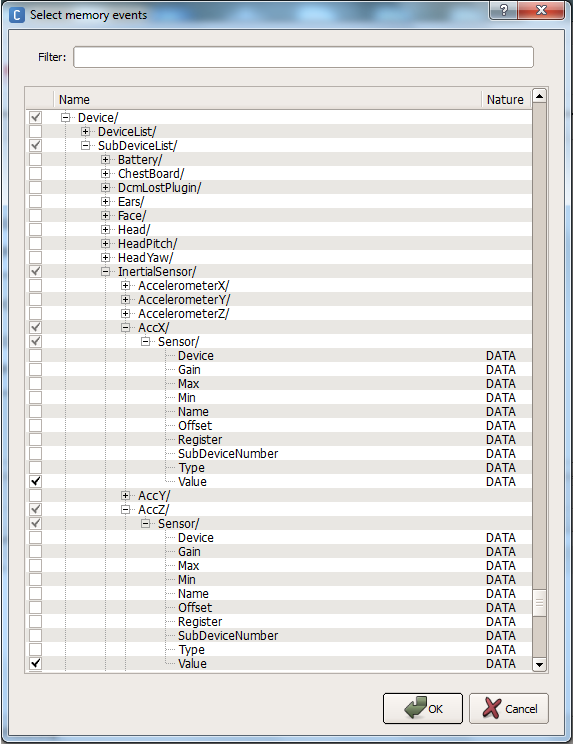
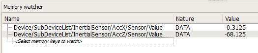
4. The two values will be shown in the memory watcher window. At the bottom you can alter the period of update. In addition, you can export this data to a .CSV file by clicking the “Start Recording” button:
5. We can also view and graph this data in the Monitor Desktop program that comes packaged with the NAO. In the same folder as the Choreograph application, open up the Monitor Desktop application.
6. When it opens, choose the top “New configuration file” option.

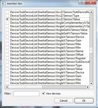
7. A window will popup displaying all the bits of data we can monitor. In the bottom of the window click the checkbox titled “view devices”. Scroll down through the various selections and choose the same two devices as we had viewed before: “Device/SubDeviceList/InertialSensor/AccX/Sensor/Value”, and “.../AccY/Sensor/Value” and “.../AccZ/Sensor/Value”:
8. Save the selection as a sample .XML file, and then the main viewing window will show.
9. In the bottom left corner of the new window, check the boxes next to “Watch All” and “Graph All”. This will graph the variables we selected. Finally, change the Subscription Mode to “Every <nb> ms”. The default value in the dialog that pops up is fine. This is how often we refresh the sensor values in the graph.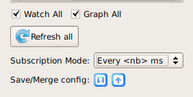
10. Now the x, y, and z axis accelerometer readings will appear on the graph. Try turning the NAO in all directions. Determine what direction each of the three axes measure acceleration along.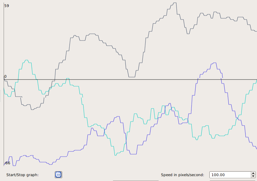
11. (Optional) Examine some of the other sensor readings. Some good ones to try are any of the Device/SubDeviceList/JOINT/Position/Sensor/Value, which returns the measured joint angle, or Device/SubDeviceList/InertialSensor/(AngleX, AngleY, AngleZ, GyrX, or GyrY)/Sensor/Value. Try to figure out what these measure on your own.
Teaching Tips:
Lesson Plan:
Trigonometric Functions of an Angle.
Objective:
The students will be able to locate a point in a coordinate plane by distance (r) and angle (θ) given its coordinates (x, y).
Common Core State Standards:
G-SRT.8. Use trigonometric ratios and the Pythagorean Theorem to solve right triangles in applied problems.★
Materials:
Cartesian coordinate system on transparency, chalkboard, or LCD projector
Scientific calculator
Vocabulary:
adjacent, angle, Cosine, degrees, distance formula, initial side, opposite, Pythagorean Theorem, radians, Sine, Tangent, terminal side
Procedure:
- Plot the point A (3, 4) on coordinate plane. Ask students to find the distance from origin to point A. Class discussion: Based on their previous experience, students may use Pythagorean Theorem or distance formula. Go over both methods, drawing the straight line distance from origin to A and labeling it r. Have students come up with the formula of r to be {{formula:r = \sqrt{x^2+y^2}}} . Students should add both methods and formula to notes. Give students a few points from first quadrant to calculate r for.
- Refer to previous class discussion after the human Cartesian plane activity, about what else is needed to get to point A, given only r. Students should come up with the need of an angle. Have students label the x-axis as the initial side and y-axis as the terminal side. Students should define both terms in their notebook. Students should label the missing angle θ.
- Define Sine, Cosine, and Tangent using x and y. Define again using side opposite, side adjacent, and hypotenuse. Students are to record in notebook.
- Review radians with students. Go over procedure for putting calculators in radian mode. Using the previous points that students calculated r for, have students find θ in radians.
- Discussion for later class: How would we locate points in a Quadrant II, III, and IV? Would r change or θ? How would they change? If given (r, θ) in a human Cartesian plane, would you move left or right then walk or vice versa? Define Cosecant, Cotangent, and Secant.
Assignment/Extension:
- Assign a worksheet or book problems that has students plotting points and finding the distance and angle.
- Give students a point in Quadrant II, III, or IV and have them find the distance and angle.
- Have students visit these two websites
//zonalandeducation.com/mmts/trigonometryRealms/TrigFuncPointDef/TrigFuncPointDefinitions.html (can check worksheet answers approximately)
//www.slideshare.net/guest793408/trigonometric-function-of-any-angle
(explains points in other quadrants, use as an overview, future lesson still needs to be taught)
Lesson Plan:
Trigonometric Functions of an Angle - Extension
Objective:
The students will be able to find the x-coordinate, y-coordinate of a point, given (r1, θ1) and (r2, θ2).
Common Core State Standards:
G-SRT.6 Understand that by similarity, side ratios in right triangles are properties of the angles in the triangle, leading to definitions of trigonometric ratios for acute angles.
G-SRT.8 Use trigonometric ratios and the Pythagorean Theorem to solve right triangles in applied problems.★
Materials:
Cartesian coordinate system on transparency, chalkboard, or LCD projector
Scientific calculator
Graph paper
Centimeter rulers
Procedure:
- Review the Sine, Cosine, and Tangent functions with students.
- Give students a point A (10 cm, 30 degrees). Have students draw picture to scale, labeling r and θ, and x and y. Have students measure and record x and y. Students should check measurements by calculating x and y using trigonometric functions. Discuss any differences. Repeat this with B (5 cm, 60 degrees) and C (12 cm, 45 degrees), each point being plotted on new graphs.
- Now have students plot point A, and then from A go the distance and angle of point B. (This is essentially adding vectors tail to tail, but we are looking for coordinates of B, not the resultant vector. This can later be discussed when teaching vectors). Have students come up with a real world example to illustrate what is happening. An example would be: I started hiking from my campsite at a 30 degrees for 10 miles. I then turned 60 degrees and continued walking 5 more miles to my friend’s campsite. How many miles would I have walked to my friend’s camp, had I gone due east and then north from my campsite?
- Have students share their examples or come up with a class example.
- Students need to calculate missing distances by creating two right triangles. The first right triangle is made by dropping a perpendicular from point A to the x-axis. Students can find xA value by using the Cosine function, and yA value by using the Sine function. The second right triangle is made by dropping a perpendicular to the horizontal line containing point B (students may have to find a different angle than the given one to calculate distances). Students can find xB value by using the Cosine function, and yB value by using the Sine function. To find the location of point B from the origin, add x and y values together (xA + xB, yA + yB). Students should realize the x-coordinate is how many miles I hiked due east and the y-coordinate is how many miles I walked north. Students can check answers with their scale drawing and compare results.
- Class discussion:
- What was the total distance hiked in the initial problem?
- What would the total distance hiked have been, going due east and then north?
- Which was the longer walk?
- How easy is it to walk a straight line distance in the woods? How are streets laid out in a town, at angles, or perpendicular and parallel?
Assignment/Extension:
Have students repeat process with points B and C. Students should also create a real world example to go with it.
Sensors and Actuators
Besides the sensors described earlier, the NAO also has an internal gyroscope and accelerometer inside its torso. The internal gyroscope and accelerometer function like the inner ear, which provides a sense of balance for humans. The gyroscope measures angular velocity (how fast the robot is turning). The accelerometer measures acceleration (which way gravity is pointing). Together, the gyroscope and accelerometer can tell the NAO if it is upright, lying on its back, or lying on its front. Additionally, the two sensors let the NAO know if it is falling down, so it can brace itself for a fall with its arms.
Actuators on a robot refer to its joint motors. The NAO has 21 different motors that can be controlled separately. There are two motors on its head/neck, two for each shoulder, two for each elbow, five for the hips, one for each knee, and two for each ankle. In Module 4, we moved many of these motors to make the NAO dance.
Each motor on the NAO is coupled with a sensor, called an encoder. This sensor measures how far each motor has turned. This is known as the motor’s angle of rotation. For example, the sensor on the elbow joint is able to tell if the arm is straight or bent at an angle.
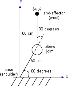
Using the angles of rotation of its joints, the NAO is aware of the pose of its entire body. For example, the NAO can calculate how far the hand is from the head. It does so using a kinematic chain, which essentially uses trigonometry to calculate relative positions of joints. In the figure below, we show a two-link arm with an elbow joint. Using the length of the arms and the angle of the elbow, we can calculate the position of the end-effector (the wrist) relative to the base (the shoulder).
![]()
Teaching Tips:
You can download the code for this module here
Advanced Task: A Bright Idea
In a previous module, we used the foot bumpers to toggle between four states. Here we’ll use the three buttons on NAO’s head to toggle between eight states. Things are becoming unwieldy using Choregraphe boxes, so we’ll switch to using Python. Each of the three head buttons will control one of the three color components: red, green and blue. By combining these colors, we can make others. For example, red and blue together will make purple, and red and green make yellow.
1. First, add a new box python block to blend the lights. Add three “bang” inputs, named “red”, “green”, and “blue”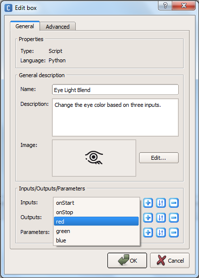
2. Add a Tactile Head box (in the Sensors category), and connect the boxes as shown below. The three outputs of the Tactile Head box trigger when the front, middle and rear buttons on the head are touched.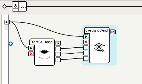
3. Double-click on your custom box to edit the source code. Here you need to write a code in Python in order to light the LED triggered by the input from the proper tactile head sensor.
Hint: The colors are set using binary 24-bit RGB values. The last eight bits are the blue component, the preceding eight bits are the green component, and the eight bits before that are the red component. So, written in hexadecimal, 0xFF0000 is red, 0x00FF00 is green, and 0x0000FF is blue.
4. Now run the behavior. Experiment with all eight different color combinations.
5. (Optional) Draw the finite state machine to describe the behavior we just created. How many states are there? What are the transitions between the states?
Teaching Tips:
You can find the code for this module here
Advanced Task: Mirror, Mirror on the Wall
Another sensor of the NAO, often overlooked, is its encoders. These sensors measure the angles of all of the NAO’s joints. In this task, we will disable stiffness on one of the NAO’s arms so that it can be moved freely. Then, we will use the encoders to read the positions of the arm joints, and mirror these same positions on the NAO’s other arm. In this way, by moving one arm, the other arm will follow.
1. Create a Bumpers box, and connect it to a custom Mirror Joints (python) box as shown below. Hitting the left bumper will start the behavior and hitting the right bumper will stop it.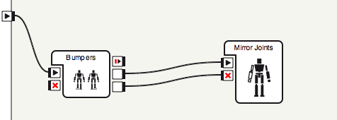
2. Create a Python code that will make the right arm stiff and left arm unstiff ( the mirroring arm). You code needs to check the values of the right arm and make the left arm get these values and move in a way that mirrors the left arm.
3. Run the behavior. Press the foot bumper, and move the robot’s arm around. Check that the other arm mirrors the same position.
Teaching Tips:
- Implement the eye blending task (A Bright Idea) using a finite state machine composed of Choregraphe boxes. Compare the difficulty of adding additional states using boxes versus Python code.
- Building on the arm mirroring task, make it so tapping the head switches which arm is being mirrored.
Hint: this will require an additional input and calls to setStiffnesses. Also, the state of the behavior will now have two features: whether or not the behavior is active, and which arm is being mirrored. - Start with the eye color blending task, and make it so you control the intensity of each color using the foot bumpers (so don’t always use 0xFF as the component). Make one bumper toggle between colors, and show the color component being modified on the feet LEDs. When the other foot bumper is pressed, increment the current color component by 0x10. Be sure to handle wrap-around properly: no color component can exceed 0xFF.
- Make the robot’s head track his own hand. Disable stiffness on the arms, and get the hand and head positions with the ALMotion method getPosition. Using setAngles, make the NAO’s head look in the direction of the vector from the head to the hands.
(Optional) Switch which hand the NAO looks at when the head tactile sensor is touched.
Teaching Tips:
Solutions
Basic:
- Where are the NAO’s two cameras located?
On its chin and forehead.
- How many microphones does the NAO have and where are they?
Four. Two in the ears, one on the back of the head and one on the forehead.
- What touch sensors does the NAO possess?
Two foot bumpers, three head touch sensors, a chest button, and foot pressure sensors.
Intermediate:
- What are the two main components of a finite state machine?
States and transitions.
- Explain when the two outputs of the Bumpers box are triggered.
One is triggered when the left bumper is pressed, the other is triggered when the right bumper is pressed.
Advanced:
- Explain what the gyroscope and accelerometer measure.
The gyrometer measures angular velocity and the accelerometer measures acceleration (e.g., gravity).
- Which three body sections can the NAO’s motors be grouped into?
Legs, arms and head/neck.
- What do encoders measure?
The position/angle of a joint.
- Explain at a high level how the NAO can know the position of its hand relative to its feet.
It knows the position of each joint, and can compute the transformation from this information.
- What three primary color components determine the color emitted from an LED?
Red, green and blue. - What is a boolean variable?
A variable that is either true or false.
- The finite state machine with buttons toggling two binary variables had four states, and the one with three binary variables had eight states. How many states does an FSM with four binary variables that you can toggle have? Five binary variables? Ten binary variables? N binary variables?
16, 32, 1024, 2n
- True or False: Everything on a digital computer is stored in binary.
True.
- How many different colors can be represented in the 24-bit RGB format?
224 - Write the RGB value for the color purple in hexadecimal.
0xFF00FF
- Compute 00110101 | 10011010 (binary), 0x7C | 0x5B (hexadecimal), and 118 | 201 (decimal).
10111111, 0x7F, 0x76 | 0xC9 = 0xFF = 255
Questions
Basic:
Intermediate:
Advanced: